Be the band.
introduction Modular components Saddle Pickups Pagoda Shim Hexpander Traction Switch Program Up/Down Switch *optional* Tone Control 1/4” Jack and 9v Battery Connector installation Locating ghost® Components Tools Required Do not file saddles! Saddle Pickups & Pagoda Shim Putting plugs onto pickup wires Installing Hexpander & 13-pin jack Mounting the Tone Control Variable Control Layouts Control Knobs Wiring Connections Diagram technical details Component Dimensions Mounting hole diameters Part Number
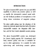
introduction The ghost Acoustic/MIDI system lets you add MIDI capability to almost any acoustic guitar, as well as amplify the instrument’s natural sound without the feedback problems of microphones or the string choice restrictions of magnetic pickups. The ghost saddle pickups turn the vibrations of the strings into electrical signals that drive both of the ghost Acoustic/MIDI modules: the Hexpander MIDI interface, and the Tone Control adjustable acoustic preamp.
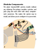
Modular Components The ghost Acoustic/MIDI systems installs without any soldering. The pickups, modules, switches, and jacks plug into each other with small, computerstyle connectors. This makes the system easy to install, and allows you to configure it to your needs.
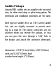
Saddle Pickups Acoustic/MIDI saddles sets are available with two notch sizes, for either steel-string or nylon-string guitars. The dimensions and installation procedures are the same. Both types of saddles fit in an 1/8”(3.2mm) saddle slot, and are slightly oversized to permit sanding to a snug fit. The plastic connectors are not attached when you receive the pickups, so that you can pass the wire through a 7/64” hole in the bridge, and attach the connector afterwards. dimensions: 0.130”(3.3mm) thick, 0.
Pagoda Shim The Pagoda Shim goes in the saddle slot and provides six “steps” at different heights for the saddles to sit on, resulting in an 18” radius. For guitars with flat fingerboards, the Pagoda Shim is not used. It doesn’t matter which way the Pagoda Shim is inserted.
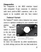
Hexpander The Hexpander is the MIDI interface board with integrated 13-pin connector. It interfaces with most pitch-to-MIDI converters, and is designed to be installed with the Tone Control TraktionTM Switch The TraktionTM Switch selects between two output curves to optimize tracking for your converter and playing style. The TraktionTM switch is located in the slot below the 13-pin jack, and slides left for AXON Roland, and right ROLAND for Axon.
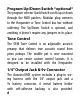
Program Up/Down Switch *optional* The program selector QuickSwitch scrolls up or down through the MIDI patches. Modular plug connects to the Hexpander or Tone Control bus bar without soldering. The Up/Down Switch is optional, and omitting it doesn’t require any jumpers in its place. Tone Control The OEM Tone Control is an adjustable acoustic preamp that delivers true acoustic sound from piezo pickups. The middle pot is wire mounted so you can create custom control layouts.
installation Installing the ghost Acoustic/MIDI system requires some permanent modification of the instrument, including holes through the sound board for the pickup wires and preamp controls, and a hole in the side for the 13-pin jack. If you’re uncomfortable with any of the steps in this manual, please find a qualified guitar technician to do the work for you.
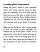
Locating ghost Components Adding the ghost® system to your instrument begins with careful planning. Begin by plugging the components into each other and lay them out on top of the guitar to decide the location of each component. Choose locations that are convenient for you, and look for space conflicts with structural parts on the inside of the guitar. Make sure that the harness wires are long enough to reach the location of each component.
Tools Required Electric drill and bits: 5/16” (12” long recommended), 9/32”, 1/4”, 7/64”, 1/16” Square file for 13-pin jack hole Phillips screw driver for mounting 13-pin jack X-Acto knife masking tape 5/16” 9/32” 1/4” 7/64” 1/16” 9
Do not file ghost saddles! Do not adjust the height of the strings by filing the string slots. This will alter the relationship between the string and the encapsulated pickup, and change the output unpredictably. If you need to adjust the height of an individual string, either carefully file the Pagoda Shim, or file the bottom of the saddle, being careful not to damage the wire. The saddles can be sanded to adjust the thickness to fit a 1/8” (3.
Saddle Pickups & Pagoda Shim The saddles pickups fit in a 1/8” (3.2mm) saddle slot. They are slightly oversized to permit sanding to a snug fit. Each saddle is marked with a dot to orient the pickup properly. This dot must face towards the fretboard so that the pickup senses the string optimally.
For steel-string guitars and other guitars with radiused fingerboards, the Pagoda Shim lies in the bottom of the saddle slot, and the pickup saddles sit on top of it. It doesn’t matter which way the Pagoda Shim is inserted. You may need to rout your saddle slot deeper to accommodate the pagoda shim. The pickup saddles should not protrude more than 1/3 of their height out of the saddle slot.
the crimps so that the catches on the plastic housing will engage the crimps when they are fully inserted. If you need to remove the housing, carefully lift both catches at the same time using an X-acto knife with a prying motion, and withdraw both crimps at the same time.
Installing Hexpander & 13-pin jack For instruments with solid-wood sides, reinforce the area where you are going to cut the hole for the 13-pin jack by gluing a small piece of 3/32” aircraft plywood inside the guitar. This reinforcement protects against cracking the wood, and makes the 13-pin jack stronger in case you step on your cable. Aircraft plywood is available at most hobby shops, and can be stuck on using regular wood glue (white) or carpenter’s glue (yellow).
a rectangular mounting hole in the body. Choose a location for this hole, checking that there is room for the Hexpander behind it, and that the ribbon cable will reach from here to the Tone Control Module. 13-pin Jack Template The size and placement of this hole can be determined using the full-size template on the following page.
13-pin Jack Template Cut out this full-sized template and use it to mark the location of the holes to drill for mounting the 13-pin jack on the edge of your guitar.
Tape the template to the edge of the instrument, and mark the center of the circles onto the guitar by tapping through the template into the lacquer using a center punch and a small hammer. Using an X-Acto knife, slice through the template along the edges of the inner rectangle, etching lines in the lacquer to mark the edges of the mounting hole. Remove the template and make sure these lines connect in the corners (this prevents your lacquer from chipping beyond the scratched lines when you begin drilling).
Using a 1/16” bit, drill the four holes for the mounting screws in the outer most marks to a depth of 1/4”. Make these holes perpendicular to the surface. Using the 7/64” bit, drill the inner four marks, defining the four corners of the mounting hole.
Using a 5/16” bit, drill holes within the inner rectangle to remove most of the wood in the cavity.
Using a file or a Dremel rotary tool, remove the remaining wood to edges of the marked rectangle. Be careful not to enlarge the mounting hole beyond the lines, as the jack plate fits quite precisely to these dimensions. Remember, this cavity does not have to be neat and smooth, as it will be hidden completely by the jack plate.
Mounting the Tone Control Carefully consider the placement of the Tone Control module, not only in terms of locating the controls conveniently, but also making sure it will fit in the guitar as you expect. Check before you drill, for braces, kerfing, or other obstructions on the under side of the guitar top.
ited by the wiring harness on the middle pot, and placement of the Tone Control itself. Check inside the guitar to make sure there are no obstructions, and that the harnesses to the other components are long enough to reach. Mark the location of the holes on the top through the centers of the washers, then remove the washers and set them aside. Drill three 9/32” (7.1mm) diameter holes to mount the potentiometers. Two of these holes must be 2-1/2” (63.
Control Knobs A set of three, stacked rosewood knobs is available from Graph Tech as a separate item, with a 1/16” hex key included for installation. Or you can provide your own knobs. Secure the knobs onto the pot shafts by means of the set screws. Leave a little clearance between the inner and outer knobs so that they turn independently. Pot Shaft Diameters: outer, 0.236” (6.0mm); inner, 0.139” (3.
Wiring Connections Diagram HEXPANDER J22 J26 J24 J27 J25 1 2 3 4 5 6 E B G D A E + 24
TONE CONTROL Program Down Up 9v Tip Bu Y Treble Bass Vi R Bk Mid Sweep Mid Tone R Ring + Acoustic Vol. MIDI Vol.
technical details Component Dimensions Hexpander: 1-3/16” x 2-1/2” (30.2 x 63.5mm) Tone Control: 1” x 3-1/2” x 5/8” (25.4 x 89 x 15.9mm) Mounting Hole Diameters Volume/Tone/Mid-Sweep pots 9/32” (7.1mm) Program Selector Switch 1/4” (6.4mm) Output Jack 3/8” (11.
installation notes 27
new sound discoveries 28
friends who’ve got to see this...
www.graphtech.com sales@graphtech.