
Instructions / Assembly

www.grapesolar.com
Tel. 1-877-264-1014 (toll free), 1-541-349-9000, Fax: 1-541-343-9000
4
GS-540-KIT-BT PHOTOVOLTAIC POWER
GENERATION SYSTEM
CONFIGURATION MANUAL Rev. 180601
Valid from June 2018
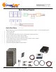
Step 5: Continued from last page.
3-panel T-branch connection
Step 6: Connect the solar connector outputs of the T-branch connect-
ors to the solar connectors of the 15-foot extension cables (note:
fuses not shown below).
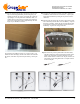
Step 7: Then connect the solar connector outputs of the
15-foot cables to the 6” solar connector-to-bare wire
pair as shown below:
MC4 to bare connecon
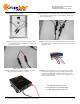
Step 8: Connect the bare wire end of the red cable to the “PV Posi-
tive” input of the controller, and the black cable end to the “PV
Negative” input .
Step 9: Connect the red (positive) and black (negative) 4
awg 5-foot cable from battery to inverter
Step 10: Uncover the panels. As the day progresses, you should
see the battery capacity percentage increase until the charge
controller is in float mode. At this point the battery can be
used to provide power (turn the inverter on and plug your AC
devices into it for power).
For additional information, see
www.grapesolar.com/manuals.html
Or email support@grapesolar.com