
Instructions / Assembly

www.grapesolar.com
Tel. 1-877-264-1014 (toll free), 1-541-349-9000, Fax: 1-541-343-9000
3
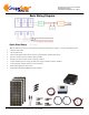
Step 2: For optimum output, place the panels so they are fac-
ing due south at approximately the same angle as your
latitude, in full sun. If you are connecting the system dur-
ing daylight, cover the panel with cardboard, cloth, or a
similar option so that it does not output power. Place the
panel so it is facing due south at approximately the same
angle as your latitude, in full sun.
GS-540-KIT-BT PHOTOVOLTAIC POWER
GENERATION SYSTEM
CONFIGURATION MANUAL Rev. 180601
Valid from June 2018
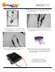
Step 3: Mount the controller if desired (note that it must be in
a NEMA-4 rated enclosure if it is outdoors). Open up the
input/output terminals by turning the top screws counter-
clockwise.
Step 4: Attach the lug end of the red cable to the positive termi-
nal on the battery and the bare end to the Battery + input on
the charge controller. Attach the lug end of the black cable
to the negative terminal on the battery and the bare end to
the Battery - input on the charge controller.
If your battery has sufficient charge (11.5 volts or more), you
should see the LCD display activate. This means the controller
has power (controllers are powered by the battery, not the pan-
els).
Step 5: Connect the positive panel leads to the inline fuses,
and then connect the positive and negative outputs of the
panel to the appropriate T-branch connectors, as seen
below. Panels 2 and 3 connect to the 1st pair, and the out-
puts of that 1st pair along with Panel 1’s outputs connect
to the second pair.