
Installation Guide


2635 W. 7
th
Place, Eugene, Oregon 97402, USA 9 Valid from March 2017
www.grapesolar.com
Tel: 1-877-264-1014 (toll free), 1-541-349-9000, Fax: 1-541-343-9000
PHOTOVOLTAIC MODULES SAFETY
AND INST
ALLATION MANUAL Rev.
O
VALID IN NORTH AMERICA ONLY
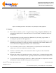
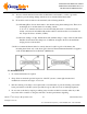
1 Stainless steel M5 nut
2 Stainless steel cupped M5 washer
3 Stainless steel flat M5 washer
4 Stainless steel M5 serrated washer
5 Grounding lead
6 Stainless steel M5 bolt
Figure-1 Grounding panel frame with stainless steel grounding & bonding equipment
5. Mounting
5.1 The modules can sustain a positive or negative design loading of 30 lbs/ft
2
(1600 Pascal). The
maximum mechanical load on the module must not exceed 45 lbs/ft
2
(2150 Pascal) under any
circumstance.
5.2 Each module must be securely fastened at a minimum of 4 points using support frames or
mounting kits specialized for PV applications.
5.3 Panels may be mounted at any angle from vertical to horizontal orientation. However, to obtain
maximum yield from the PV system, the direction and tilt angle for the modules shall be set to
receive the incident sunlight perpendicularly to the module surface.
5.4 For roof mounted systems, at least a 4 inch clearance is required between the module back
surface and roof for rear ventilation and module cooling.
5.5 Clearance of 1/24 inch (1mm) or more between modules is required to allow for thermal
expansion of the frames.
5.6 Keep the back surface of the module free from any foreign objects or structural elements which
could come into contact with the module, especially when the module is under mechanical load.
5.7 To prevent water from entering the junction box, which could result in a safety hazard, modules
should not be mounted with the front/top glass facing downward.