
Instruction Manual

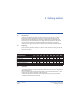
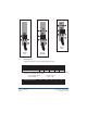

2.3.1 Assembly- Allmodels(seeFig1)
Removethethermostatmountingplatefromthetankbyunscrewingthefourblackknobs
locatedinthecornersoftheplate(1a).
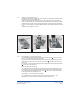
FeedtheOptimathermostatthroughtheholeinthebridgeplate,beingcarefulnotto
forceit. Thethermostatcanbelocatedeitherfacingforwardorfacingtotheleft.Ineither
positionthreeoftheholesinthemountingplatewilllineupwithholesinthethermostat
unit(1b). ScrewtogetherusingM3x6stainlesssteelscrewssuppliedwiththethermostat
unit.
Reattachmountingplatetounit(1c).
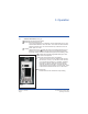
2.3.2 PowerSupplyR1,R2,R3(seeFig3a/3b)
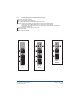
PowerSupplyR4,R5(seeFig3c)
PowerSupply-115vmodels(seeFig3d/3e/3f)
The Thermostatunittakesitspowerfromthemainssocketoutlet()ontherearofthe
coolerunit,viatheinterconnectingpowercable.
Plugoneendofthisinterconnectingcableintothepowerinletsocketontherearofthe
Thermostatunitandtheotherendintothesocketoutlet()mountedontherearofthe
coolerunit.
Plugthemainscable(suppliedwithOptimathermostat)intothefusedpowerinletsocket
()ontherearofthecoolerunit.
The Thermostatunitisconnectedfromthetwinfusedpowerinletsocketdirectlytothe
mainswiththeIECcablesuppliedwiththeOptima Thermostat. Therefrigerationunitis
connectedfromthetwinfusedpowerinletsocket()directlytothemainswiththeIEC
cablesuppliedwiththeRefrigerationunit.
The Thermostatunitisconnectedviaitspowercorddirectlytothemains. The
refrigerationunitisconnectedviaitspowercorddirectlytothemains.
Fig1a
Fig1b Fig1c
screw
screw
screw
Page7
Lowtemperaturebath/circulator
Operatinginstructions
Version4-Jan2010
2
2
3
3