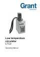
Low temperature circulator LTC2 Operating Manual
Grant Instruments, based near Cambridge, England is a world leader in the manufacture and design of equipment for sample preparation, scientific analysis, data acquisition and data analysis providing solutions to the global scientific and industrial markets. Standards Compliance and Quality Grants’ brand and reputation are based around quality, reliability and accuracy. We ensure our products stringently meet all necessary international safety standards.
Contents Contents 1.0 Use of products 2.0 How to use this operating manual 3.0 Safety information 3.1 Safety compliance 3.2 Safety symbols 3.3 Safety warnings 4.0 Operating instructions 4.1 Unpacking instructions 4.2 Recommended liquids 4.3 Installation 4.4 Electrical supply 5.0 Operating procedures 5.1 Operation 5.1.1 Liquid level 5.1.2 Operation above 60°C 5.1.3 Using the pump 5.1.4 Emptying the LTC2 5.1.5 Setting up and switching on 5.2 Using the LTC2 5.2.1 Product description, control unit 5.2.
12.0 Contact Grant Instruments 13.0 Compliance Notes 30933 V2 Page 3 24 24 25 LTC2 Operating Manual www.grantinstruments.
1.0 Use of products The following products are covered by this operating manual: LTC2 & LTC2L The products listed above are low temperature circulators designed for indoor laboratory use by a professional user. The LTC2 consists of a TC120 immersion thermostat combined with an R2 refrigeration unit, with insulated hoses and clips to allow circulation of temperature control fluids to external equipment. 2.
3.3 Safety warnings Read the whole of these instructions. Safety may be impaired if they are not followed. For the LTC2, only use liquids specified in these operating instructions, within the specified temperature range. If the alarm lamp is illuminated the liquid temperature may be above its recommended maximum. Do not inhale the vapours given off as they may be toxic. Liquids should be safely discarded and replaced. Do not use the LTC2 with flammable heat transfer liquids.
4.0 Operating instructions 4.1 Unpacking instructions Standard equipment includes: LTC2 low temperature circulator Pump connector kit 4 x Jubilee clips 6m of insulated hose Mains cord The LTC2 weighs 25kg. Take necessary precautions when lifting. Remove packing materials carefully and retain them for future shipment or storage of the equipment. 4.2 Recommended liquids The following table lists the recommended liquids for different temperature ranges.
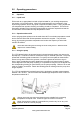
4.3 Installation After transportation, let the unit stand in its intended working position for six hours. This is to allow the oil to drain to the bottom of the compressor. This is normal procedure for refrigeration compressors. Allow at least 100mm clearance from obstructions on all sides so that there is free air flow through the unit, from the front to the back (this also has the advantage that air is not blowing directly out of the sides onto instruments next to the LTC2).
5.0 Operating procedures 5.1 Operation 5.1.1 Liquid level Fill the tank to an appropriate level with a liquid suitable for your working temperature; see section 4.2 for liquid options. Allow for thermal expansion and contraction of the liquid during operation and for any liquid in external circulation paths. If using liquids that can evaporate then periodic checking and refilling should be completed.
Never use silicone oil with silicone tubing. Pumping heat transfer liquid around an external system can lead to hazards that are outside the control of Grant Instruments. It is essential that the user conducts a risk assessment of the entire equipment installation to ensure that correctly rated materials have been used throughout and that the system can be used safely. 5.1.4 Emptying the LTC2 The LTC2 tanks should be emptied to a safe level prior to moving.
5.2 Using the LTC2 5.2.1 Product description, control unit Alarm light Heater on light Over-temperature dial Display Function button Select button Control dial Pump outlet plate Float switch 5.2.
5.2.3 Product description, refrigeration unit front panel (grille removed) Power switch Over temperature protection reset Freezing protection, 5˚C switch Drain port Drain insert Condenser fins The refrigation unit has a resetable over temperature protection which protects the unit from overheating. This will be actuated when the working fluid temperature is between 110°C and 120°C.
5.2.4 Product description, refrigeration unit rear panel Not used on this model Power supply for accessory pumps Not used on this model Power supply for accessory pumps Power supply for control unit (220-240V units only) Mains fuses Mains inlet and fuses Mains cable inlet 220-240V unit 5.2.5 110-120V unit Setting the control temperature The temperature of the circulation liquid can be set using the S button. 1. Whilst the display is showing the bath temperature, press the S button.
5.2.7 Setting the over-temperature thermostat An over-temperature cut-out dial with a temperature scale is located at the top right of the unit. The over-temperature probe independently monitors the bath temperature and switches the heater off if it goes above the cut-out threshold. For the LTC2, the temperature cut-out threshold can be adjusted for convenience. Coarse setting of the over-temperature thermostat Rotate the temperature cut-out dial in line with the marked scale to the desired setting.
Preset Set temperature range t-1 37°C t-2 56°C t-3 72°C 5.2.9 Running a bath preset 1. Press the F button and rotate the dial until the display shows the correct preset. 2. Press the S button to select the preset. 3. Press the S button to set the bath to the preset temperature. 5.2.10 Completing a calibration The LTC2 allows a two point calibration to be completed. The calibration menu can be accessed by simultaneously pressing the F and S buttons for about 5 seconds.
Setting the high temperature offset 1. Adjust the set temperature to the required high temperature calibration point. 2. Allow the unit to stabilise for at least 5 minutes after a stable temperature condition has been achieved. 3. Measure the liquid temperature by placing a reference thermometer into the centre of the bath. 4. Press the F and S buttons simultaneously for approximately 5 seconds until “LCAL” is shown. 5. Rotate the dial until the display shows “HCAL” and press the S button to select. 6.
Note: the LTC2 will continue to control at the set temperature after the timer reaches zero – the heater will not switch off. 5.2.14 Cancelling the timer The countdown timer can be easily cancelled. 1. Press the F button twice – the display will show “Cloc”. 2. Press the S button to select. 3. Use the main dial to select “Off” and press the S button to select. The display will revert to the bath temperature and the timer will be cancelled. 5.2.
6.0 Technical specifications 6.1 Operating conditions Ambient temperature range 5 to 40°C Altitude above sea level Up to 2,000m (6,500ft) Operating environment Indoor use only Maximum relative humidity 80% RH up to 31°C decreasing to 50% RH at 40°C 6.2 Electrical details Mains supply: Pollution degree: Installation category: 220-240V @ 50Hz or 110-120V @ 60Hz 2 II Mains supply voltage fluctuations are not to exceed ±10% of the nominal supply voltage. 6.
7.0 Technical Tips 7.1 Which water should you use in your bath? For the long-term reliability of water baths it is important to use oxygenated water that is free from ions and minerals that can cause corrosion of stainless steel. We recommend the use of distilled water and de-ionised water from modern ion exchange systems that do not use salt back flushing to regenerate the ion-exchange cartridges. Stainless steel is protected from corrosion by a layer of chromium oxide.
7.3 How to prevent algae and bacteria? Water baths provide the ideal environment for the growth of micro-organisms. If left uncontrolled the growth of these organisms can result in a range of serious problems and health risks from pathogenic bacteria. The growth of algae on the surface of parts will cause biofouling which can reduce performance. Micro-organisms that produce acidic metabolic by-products can cause bio-corrosion by depolarisation of metal surfaces.
Clean the outside of the equipment with a damp cloth, using water only. Do not use chemical cleaning agents. Before using any other cleaning or decontamination method, check with Grant Instruments or your local representative to make sure that the proposed method will not damage the equipment. Scale on immersed parts can be removed using chemical de-scaling products designed for use on equipment that has metal parts.
9.6 Service If service is required, switch off the unit and contact Grant Instruments or your local representative for repairs. Please note, all returned units must be accompanied by a Return Materials Authorisation (RMA) number, obtainable by contacting the Grant service department (details below). Service Department Grant Instruments (Cambridge) Ltd Shepreth Cambridgeshire SG8 6GB UK Tel: +44 (0) 1763 260 811 Fax: +44 (0) 1763 262 410 E-mail: labservice@grantinstruments.com 10.
11.0 Troubleshooting Symptom Possible cause Action required Display shows “Cut” Over-temperature cut-out has operated Check the set temperature is correct and that the over-temperature cut-out temperature is set at least 5°C above the set temperature. Refer to section 5.2.7 for setting instructions. If the over-temperature cut-out temperature is correctly set but the unit still shows a “Cut” alarm then the unit has an internal fault and must be repaired before it is used again.
Display shows “Er L” Incorrect calibration value The low temperature calibration point is less than 40°C below the high calibration point – choose a lower temperature (see section 5.2.10). Display shows “Er d” Incorrect calibration value The calibration value is greater than 10°C from the set point – check thermometer reading and set point (see section 5.2.10). Display shows “Open” Faulty temperature probe Have a competent person check the probe for an open circuit fault or contact Grant.
12.0 Contact Grant Instruments At Grant we are continuously trying to improve the performance we offer our customers. If you have any feedback on Grant’s products or services we would like to hear from you. Please send all feedback to: Quality Manager Grant Instruments (Cambridge) Ltd Shepreth Cambridgeshire SG8 6GB UK Tel: +44 (0) 1763 260 811 Fax: +44 (0) 1763 262 410 E-mail: feedback@grantinstruments.com 13.
Notes 30933 V2 Page 25 LTC2 Operating Manual www.grantinstruments.
Grant Instruments (Cambridge) Ltd Shepreth Cambridgeshire SG8 6GB UK Tel: +44 (0) 1763 260811 Fax: +44 (0) 1763 262410 Email: labsales@grantinstruments.com www.grantinstruments.