Shaking water bath OLS200 Refrigerated immersion cooler CS200G Operating Manual
1 Safety 2 Getting Started 2 3 2.1 Unpacking 2.1.1 Shaking bath - OLS200 2.1.2 Universal Tray 2.1.3 Test Tube Tray 2.1.4 Cooler - CS200G 2.1.5 Cooling coil - CW200 2.2 Installation 2.2.1 Location 2.2.2 for operating temperatures below ambient 2.2.3 for operating temperatures above 60°C 2.2.4 Fitting the trolley 2.2.5 Fitting the tray 2.2.6 Filling 2.2.8 Connection to electrical supply 3 3 3 3 3 3 3 3 3 3 4 4 4 4 3 5 Operation 3.1 OLS 200 3.1.1 Controls and indicator lamps 3.1.
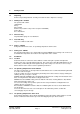
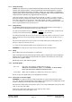
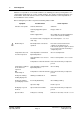
1 Safety The following symbols marked on the equipment mean:Caution: Read these operating instructions fully before use and pay particular attention to sections containing this symbol Caution: Surfaces can become hot during use. Always observe the following safety precautions Use only as specified by the operating instructions or the intrinsic protection may be impaired. After transport or storage in humid conditions, dry out the unit before connecting it to the supply voltage.
2 Getting Started 2.1 Unpacking Remove the packing materials carefully, and retain for future shipment or storage. 2.1.1 Shaking bath - OLS200 The pack should contain: shaking bath trolley drive magnet drain insert (located in a clip on the rear panel of OLS200) mains cable these instructions. 2.1.2 Universal Tray Tray fitted with springs for use with flasks. 2.1.3 Test Tube Tray Tray for use with test tube racks. 2.1.
2.2.4 Fitting the trolley Caution: The shaker uses a magnet located in the bottom of the tank. Once removed from the bath the drive magnet produces a strong magnetic field and it should be placed in a position where it cannot affect computer discs, cassettes, watches, etc. If your watch is susceptible to magnetic fields, please remove it before removing or fitting the trolley. Once the trolley and drive magnet have been fitted the stray magnetic fields are very small.
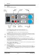
3 Operation 3.1 3.1.1 OLS 200 Controls and indicator lamps Shaking Switch Heater Lamp Power Switch Push to Reset Knob Alarm Lamp Display Set Button Shaking Knob Temperature Knob The temperature display normally shows the liquid temperature in C. When the display set C button is pressed the set temperature is shown. The temperature C control knob sets the required operating temperature. Heater lamp (orange) indicates when the heater is on.
3.1.3 Shaking Switch on shaking. In linear motion the number of strokes/minute is double the number displayed. To set the required revolutions per minute, turn the shaking/min knob until the required speed is displayed. The speed rises slowly to the set value. Following adjustment, the setting should be checked after several minutes. Stroke length for linear movement The stroke length in linear motion can be altered according to your requirement with a choice of three settings.
3.1.4 Setting the overtemperature cut-out To protect both the unit and your samples, the overtemperature cut-out should be set each time the required operating temperature is changed. Turn the overtemperature push to reset knob fully clockwise and press to reset. The cut-out is now set at its maximum. Allow the bath to stabilise at the required operating temperature. Turn the control slowly anticlockwise using a screwdriver until the red alarm lamp comes on.
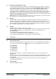
4.3 Tray for test tube racks TT200 The tray accommodates up to five test tube racks as follows: H1 test tube racks: H1-10 rack holds 48 x 10 mm tubes H1-13 rack holds 44 x 13 mm tubes H1-16 rack holds 24 x 16 mm tubes HI-19 rack holds 21 x 19 mm tubes H1-25 rack holds 12 x 25 mm tubes H1-30 rack holds 10 x 30 mm tubes 4.
5 Fault diagnosis Whilst it is not possible to cover all fault conditions, the following procedures provide guidance for solving simple faults which can occur in normal operation. The operator should not attempt to cure internal faults, but should return the unit for service to Grant Instruments' Service department or their distributor in other countries. Before starting this procedure set power and shaking switches OFF.
6 Technical specification This equipment is designed for indoor use in laboratory conditions, with room temperature between 5°C and 40°C, and 80% relative humidity up to 31°C. Performance figures apply in ambient temperature between 10°C and 35°C. Installation category II (Transient voltages). Pollution degree 2 in accordance with IEC 664. For operation at altitudes up to 2000 metres. As Grant Instruments is committed to a continuous programme of improvement, specifications may be changed without notice.
6.2 CS200G refrigerated cooler Refrigerated cooler for use in liquids between 0° and 40°C. Immersed material: the cooling coil is nickel-plated copper. Power consumption 500VA Cooler extraction @ 20°C 200 W @ 0°C 100 W Supply voltage: 230V 10% @ 50/60Hz Size: 475/320/255 Mass: 21Kg 7 Maintenance and service 7.1 OLS200 Shaking bath All Grant laboratory products are designed to comply with IEC1010-1 and can be flash tested.
7.3 Replacement of fuses WARNING: Before removing the cover, isolate from the mains power supply. Only a competent person should change fuses. 7.3.1 OLS200 Shaker bath First disconnect the mains cable from the power supply, then remove the socket end from the plug in the back of the bath. Drain the bath. Press down the fuse drawer catch (see figure 12). Pull out the fuse drawer, replace the fuse with the correct type, and replace the fuse holder.
10 Compliance 10.1 Disposal & WEEE Grant Instruments complies fully with the Waste Electrical & Electronic Equipment (WEEE) regulations 2006. We are a member of the B2B compliance scheme (Scheme Approval Number WEE/MP3338PT/SCH), which handle our WEEE obligations on our behalf. Grant Instruments have been issued with a unique registration number by the Environmental Agency, this reference number is WEE/GA0048TZ.
Front Figure 1 OLS200, CSG200 Operating Manual Page 14 15214 Ver 9 - January 2010 57U www.grant.co.
Figure 2 OLS200, CSG200 Operating Manual Page 15 15214 Ver 9 - January 2010 57U www.grant.co.
Front Figure 3 Figure 4 OLS200, CSG200 Operating Manual Page 16 15214 Ver 9 - January 2010 57U www.grant.co.
Front Front Figure 5 OLS200, CSG200 Operating Manual Page 17 15214 Ver 9 - January 2010 57U www.grant.co.
Figure 6 Layout of springs and flasks For 45 off 25ml flasks OLS200, CSG200 Operating Manual Page 18 15214 Ver 9 - January 2010 57U www.grant.co.
Figure 7 Layout of springs and flasks For 28 off 50ml flasks OLS200, CSG200 Operating Manual Page 19 15214 Ver 9 - January 2010 57U www.grant.co.
Figure 8 Layout of springs and flasks For 18 off 100ml flasks OLS200, CSG200 Operating Manual Page 20 15214 Ver 9 - January 2010 57U www.grant.co.
Figure 9 Layout of springs and flasks For 11 off 250ml flasks OLS200, CSG200 Operating Manual Page 21 15214 Ver 9 - January 2010 57U www.grant.co.
Figure 10 Layout of springs and flasks For 6 off 500ml flasks OLS200, CSG200 Operating Manual Page 22 15214 Ver 9 - January 2010 57U www.grant.co.
Figure 11 Layout of springs and flasks For 3 off 1000ml flasks OLS200, CSG200 Operating Manual Page 23 15214 Ver 9 - January 2010 57U www.grant.co.
FUSE DRAWER PUSH LEVER UP TO RELEASE FUSE DRAWER Figure 12 Replacement of mains fuses on rear panel OLS200, CSG200 Operating Manual Page 24 15214 Ver 9 - January 2010 57U www.grant.co.
OLS200, CSG200 Operating Manual Page 25 15214 Ver 9 - January 2010 57U www.grant.co.
OLS200, CSG200 Operating Manual Page 26 15214 Ver 9 - January 2010 57U www.grant.co.
Grant Instruments (Cambridge) Ltd Shepreth Cambridgeshire SG8 6GB England Tel: +44 (0) 1763 260811 Fax: +44 (0) 1763 262410 Email: labsales@grant.co.uk www.grant.co.