
User's Manual
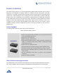
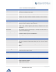
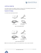
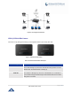
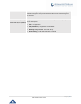
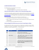
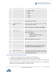
Table Of Contents

P a g e | 14
HT812/HT814 User Guide
HT812/HT814 Ports Description
The following figure describes the different ports on the back panel of the HT812/HT814.
Table 3: Definition of the HT812/HT814 Connectors
Connecting the HT812/HT814
The HT812/HT814 are designed for easy configuration and easy installation, to connect your
HT812/HT814, please follow the steps above:
1. Insert a standard RJ11 telephone cable into the p hone port and connect the other end of the
telephone cable to a standard touch-tone analog telephone.
2. Insert the Ethernet cable into the internet or LAN port of the HT812/HT814 and connect the other
end of the Ethernet cable to an uplink port (a router or a modem, etc.)
3. Insert the power adapter into the HT812/HT814 and connect it to a wall outlet.
4. Power, Ethernet and Phone LEDs will be solidly lit when the HT812/HT814 is ready for use.
Phone 1 & 2 (HT812)
Phone 1,2,3 & 4 (HT814)
Connects the analog phones / fax machines to the phone adapter using an RJ-
11 telephone cable.
WAN
Connects the phone adapter to your router or gateway using an Ethernet RJ45
network cable.
co
LAN
Connects the phone adapter to your PC using an Ethernet RJ45 network cable.
DC Power
Powers the phone adapter. (12V – 0.5A for HT812) and (12V - 1A for HT814).
Reset
Factory reset button. Press for 7 seconds to reset factory default settings.
Figure 3: HT812 Back Panel
Figure 4: HT814 Back Panel