Grandstream Networks, Inc. HT503 FXS/FXO Port Analog Telephone Adaptor HT503 User Manual Firmware Version 1.0.4.2 www.grandstream.com support@grandstream.
TABLE OF CONTENTS HT503 USER MANUAL WELCOME....................................................................................................................................................... 4 Safety Compliances ................................................................................................................ 4 Warranty ................................................................................................................................. 4 CONNECT YOUR HT503.....................
TABLE OF FIGURES HT503 USER MANUAL Figure 1: Connecting the HT503 ..................................................................................................... 5 Figure 2: Interconnection Diagram of the HT503 ............................................................................ 6 Figure 3: Uplink/Downlink Bandwidth Limitation ........................................................................... 22 TABLE OF TABLES HT503 USER MANUAL Table 1: Definitions of the HT503 Connectors ..........
WELCOME Thank you for purchasing Grandstream’s HT503, the affordable, feature rich, Analog Telephone Adaptor/IAD. The HT503 combines a sleek design with the latest technology to offer more advanced telephony features and significantly better integrated router performance than its predecessor – the HT488. It is the second ATA/IAD in the HandyTone 50x series. The HT503 functions as a true 3-in-1 gateway for PSTN network, analog telephone FXS interface and IP network.
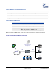
CONNECT YOUR HT503 Equipment Packaging The HT503 ATA package contains: • • • • One HT503 Main Case One Universal Power Adaptor One Ethernet Cable One HT503 Vertical Stand Connecting the HT503 The HT503 is designed for easy configuration and easy installation. Configure the HT503 following the directions in the Configuration section of this manual. 1. Connect a standard touch-tone analog telephone to the PHONE port. 2.
TABLE 1: DEFINITIONS OF THE HT503 CONNECTORS 12VDC, 0.5A Power adapter connection LAN Port (RJ-45) Connect the LAN port with an Ethernet cable to your PC. WAN Port (RJ-45) Connect the WAN port to the internal LAN network or router. PHONE (RJ-11) FXS port to be connected to analog phones / fax machines. LINE (RJ-11) FXO port should be connected to the PSTN line TABLE 2: HT503 LED DEFINITIONS LEDs POWER LED WAN LED LAN LED PHONE/ LINE LED Indicates Power.
PRODUCT OVERVIEW The HT503 is an affordable, high-quality, integrated IP telephony solution for both the residential customers and the ‘road-warriors’ who need advanced call features between traditional PSTN network and IP network. The HT503 enables IP connectivity for any phone or fax using the FXS port and a webbased GUI for easy configuration and installation.
Pass-through (pending), Fax Data pump V.17, V.19, V.27ter, V.29 for T.38 fax relay Security DIGEST authentication and encryption using MD5 and MD5-sess Physical Design Stylish and compact design; small universal power supply, ideal for travel Hardware Specification The table below lists the hardware specification of HT503.
BASIC OPERATIONS Understanding HT503 Voice Prompt HT503 has a built-in voice prompt menu for simple device configuration. The voice prompt menu is designed for the FXS port only. To enter the voice prompt menu, press *** from the analog phone connected to the FXS port.
“Restoring Factory Settings”) “Invalid Entry” NOTE: • • • • • Automatically returns to main menu “*” shifts down to the next menu option “#” returns to the main menu “9” functions as the ENTER key in many cases to confirm an option All entered digit sequences have known lengths - 2 digits for menu option. For IP address, the "*" key represent the dot "." (Like 192.168.0.26 should be key in like 192*168*0*26). Once all of the digits are collected, the input will be processed.
1. Pick up the analog phone then dial “*47” 2. Enter the target IP address using same format as above. Note: NO dial tone will be played between step 1 and 2. Destination ports can be specified by using “*” (encoding for “:”) followed by the port number. Examples: a) If the target IP address is 192.168.0.160, the dialing convention is *47 or Voice Prompt with option 47, then 192*168*0*160. followed by pressing the “#” key if it is configured as a send key or wait 4 seconds.
Three situations can follow the transfer: 1. A quick confirmation tone (temporarily using the call waiting indication tone) followed by a dialtone. This indicates the transfer was successful (transferee has received a 200 OK from transfer target). A can either hang up or make another call. 2. A quick busy tone followed by a restored call (on supported platforms only). This means the transferee has received a 4xx response for the INVITE and we will try to recover the call.
• To receive PSTN calls, pick up the phone when it rings; • To complete a PSTN call, press the PSTN access code (*00 is default, or any number configured in the web configuration) to switch to the PSTN line, listen for a dial tone, then dial the number. • If the 503 loses power or lost registration with SIP server, device will switch to mode when PSTN line will be transparently connected directly to phone connected to FXS port. It will function as a jack, enabling a direct connection to the PSTN Line.
2. If no one answers the call after 4 rings (default configuration), then the caller hears either a special continuous tone (prompting a PIN number) or a dial tone. 3. Enter a valid PIN (if configured under the BASIC configuration page). The caller will hear dial tone and be bridged to VoIP. If an incorrect PIN is input, the continuous tone prompts caller to enter a valid PIN. The caller may try 3 times to enter a valid PIN, if it is invalid the HT503 will hang up. 4.
Forward Calls to VoIP By default, each incoming PSTN call is received over the FXS port. The end-user may forward such a call to any preconfigured VoIP extension, in case the call is not answered in a certain number of rings. The Default value of the parameter “Number of Rings” is 4. This parameter located under “FXO Port” configuration page.
CALL FEATURES TABLE 6: HT503 CALL FEATURE DEFINITIONS Key Call Features *02 *03 *16 Forcing a Codec (per call) *027110 (PCMU), *027111 (PCMA), *02723 (G723), *02729 (G729), *0272616 (G726-r16), *0272624 (G724-r24), *0272632 (G726-r32), *0272640 (G726-r40), *027201 (iLBC) Disable LEC (pe call) Dial “*03” + ” number ”. No dial tone is played in the middle.
CONFIGURATION GUIDE Configuring HT503 through Voice Prompt DHCP MODE Follow Table 4 with voice menu option 01 to enable HT503 to use DHCP. STATIC IP MODE Follow Table 4 with voice menu option 01 to enable HT503 to use STATIC IP mode, then use option 02, 03, 04 to set up HT503’s IP, Subnet Mask, Gateway respectively. FIRMWARE SERVER IP ADDRESS Select voice menu option 13 to configure the IP address of the firmware server.
Configuring HT503 with Web Browser HT503 ATA has an embedded Web server that will respond to HTTP GET/POST requests. It also has embedded HTML pages that allow users to configure the HT503 through a Web browser such as Microsoft’s IE, AOL’s Netscape or Mozilla Firefox installed on Windows or Unix OS. (Macintosh OS is not included). Access the Web Configuration Menu The HT503 HTML configuration page can be accessed via LAN or WAN ports. • FROM THE LAN PORT: 1. Directly connect a computer to the LAN port 2.
Only an administrator can access the “ADVANCED SETTING”, “FXS PORT” and “FXO PORT” configuration pages. Please reference the GUI pages using the following link: http://www.grandstream.com/products/ht_series/ht503/documents/ht503_gui.zip. DEFINITIONS This section will describe the options in the Web configuration user interface. As mentioned, a user can log in as an administrator or end-user.
TABLE 8: BASIC SETTINGS End User Password This contains the password for end user to access the Web Configuration Menu. User can put new password here. This field is case sensitive with maximum of 25 characters Web Port This is the device’s internal HTTP server port. Default is 80. Telnet Server Default is set to YES. Telnet access is allowed to the device in this case. Used only for special purposes such as debugging and troubleshooting.
NAT UDP Timeout NAT TCP idle timeout in seconds. Connection will be closed after preconfigured, timeout if not refreshed. Range: 0 – 3600, default is 300 Uplink Bandwidth The maximum uplink bandwidth permitted by the device. This function is disabled by default. The total bandwidth can be set as: 128K, 256K, 512K, 1M, 2M, 3M, 4M, 5M, 10M or 15M. The primary function of this setting is to limit the uplink bandwidth for the device internal system, signaling and NATed traffic.
FIGURE 3: UPLINK/DOWNLINK BANDWIDTH LIMITATION Advanced User configuration includes not only the end user configuration, but also advanced configurations such as: SIP configuration, Codec selection, NAT Traversal Setting and other miscellaneous configuration. TABLE 9: ADVANCED SETTINGS Admin Password Layer 3 QoS Layer 2 QoS STUN Server Keep-alive interval Use STUN to detect network activity Firmware Upgrade and Provisioning Via TFTP Administrator password.
Via HTTPS Firmware Server Path Config Server Path XML Config File Password HTTP/HTTPS User Name HTTP/HTTPS Password Firmware File Prefix Firmware File Postfix Config File Prefix Config File Postfix Automatic Upgrade Authenticate Conf File Firmware Key SSL Certificate SSL Private Key SSL Private Key Password ACS URL ACS Username ACS Password Periodic Inform Enable Periodic Inform Interval Connection Request Username Connection Request Password System Ring Cadence Call Progress Tones The URL of the HTTP se
Lock Keypad Update Disable Voice Prompt Disable Direct IP Calling Life Line Mode NTP server Syslog Server Syslog Level (Note: freq: 0 - 4000Hz; vol: -30 - 0dBm) If set to “Yes”, the configuration update via keypad is disabled. Note: some informative options still will be available for users after configuring to Yes. Changing existing configuration will be impossible. Disables the voice prompt configuration. Default is “No. ” If set to “Yes” accessing integrated voice menu will be impossible.
SIP User ID Authenticate ID Authentication Password Name DNS mode User ID is Phone Number SIP Registration Unregister on Reboot Outgoing Call w/o Registration Register Expiration Local SIP port Local RTP port User account information, provided by VoIP service provider (ITSP), usually has the form of digit similar to phone number or actually a phone number. This field contains the user part of the SIP address for this phone. e.g., if the SIP address is sip:my_user_id@my_provider.
incoming INVITE SIP T1 Timeout SIP T2 Interval DTMF Payload Type Preferred DTMF method (in listed order) Disable DTMF Negotiation Send Flash Event Enable Call Features Offhook Auto-Dial Proxy-Require Use NAT IP Distinctive Ring Tone call will be rejected. If this option is enabled, the device will not be able to make direct IP calls. T1 is an estimate of the round-trip time between the client and server transactions. If the network latency is high, select larger value for more reliable usage.
Dial Plan Prefix Use # as Dial key Dial Plan IP-to-IP calling. Sets the prefix added to each dialed number. This allows users to configure the # key as the “Send” (or “Dial”) key. If set to “Yes”, “#” will send the number. In this case, this key is essentially equivalent to the “Dial” key. If set to “No”, the “#” key can be included as part of a number. Dial Plan Rules: 1. Accept Digits: 1,2,3,4,5,6,7,8,9,0 , *, #, A,a,B,b,C,c,D,d 2.
Session Expiration Min-SE Caller Request Timer Callee Request Timer Force Timer UAC Specify Refresher UAS Specify Refresher Send Re-INVITE After Fax Use First Matching Vocoder in 200OK SDP Force INVITE Preferred Vocoder G723 Rate: iLBC Frame Size: iLBC Payload Type: AAL2-G726-16 Payload Type AAL2-G726-24 Payload Type AAL2-G726-32 Payload Type AAL2-G726-40 Payload Type G729E Payload Type VAD Symmetric RTP Fax Mode Fax Tone Detection Mode Jitter Buffer Type Jitter Buffer Length Grandstream Networks, Inc.
• SRTP Mode SLIC Setting Called ID Scheme Caller ID TX Level (dB) Polarity Reversal Loop Current Disconnect Loop Current Disconnect Duration Hook Flash Timing On Hook Timing Gain High (initial 200ms, min 40ms, max 600ms) Note: not all vocoders can meet the high requirement • Medium (initial 100ms, min 20ms, max 200ms) Low (initial 50ms, min 10ms, max 100ms) Secure RTP protocol used for media transmission over VoIP. Disabled by default. Other modes are: enabled but not forced & enabled and forced.
according to the STUN client specification. Using this mode, the embedded STUN client will detect if and what type of firewall/NAT is being used. If the detected NAT is a Full Cone, Restricted Cone, or a Port-Restricted Cone, the HT503 will use its mapped public IP address and port in all of its SIP and SDP messages.
incoming INVITE SIP T1 Timeout SIP T2 Interval DTMF Payload Type Preferred DTMF method (in listed order) Disable DTMF Negotiation Proxy Require call will be rejected. If this option is enabled, the device will not be able to make direct IP calls. T1 is an estimate of the round-trip time between the client and server transactions. If the network latency is high, select larger value for reliable usage. Maximum retransmission interval for non-INVITE requests and INVITE responses.
{ ^1900x. | <=1617>[2-9]xxxxxx | 1[2-9]xx[2-9]xxxxxx | 011[2-9]x. | [3469]11 } Explanation of example rule (reading from left to right): • ^1900x. - prevents dialing any number started with 1900 • <=1617>[2-9]xxxxxx - allows dialing to local area code (617) numbers by dialing 7 numbers and 1617 area code will be added automatically • 1[2-9]xx[2-9]xxxxxx |- allows dialing to any US/Canada Number with 11 digits length • 011[2-9]x.
iLBC Payload Type: AAL2-G726-16 Payload Type AAL2-G726-24 Payload Type AAL2-G726-32 Payload Type AAL2-G726-40 Payload Type VAD This defines payload type for iLBC. Default value is 97. The valid range is between 96 and 127. Defines payload type for AAL2-G726-16. Default value is 100. Range is from 96 to 127. Defines payload type for AAL2-G726-24. Default value is 99. Range is from 96 to 127. Defines payload type for AAL2-G726-24. Default value is 104. Range is from 96 to 127.
Enable Current Disconnect Default is Yes. This value should be used in case the PSTN provider uses line power drop to indicate call completion to the end point. In this case the HT503 will search for a power drop for a preconfigured time frame to disconnect such calls from a VoIP extension. Current Disconnect Threshold (ms) This is a preconfigured value of duration for a line power drop used by specific service providers.
Saving the Configuration Changes After user makes a change to the configuration, press the “Update” button in the Configuration Menu. The web browser will then display a message window to confirm saved changes. Grandstream recommends reboot or power cycle the IP phone after saving changes. Rebooting from Remote Press the “Reboot” button at the bottom of the configuration menu to reboot the phone remotely. The web browser will then display a message window to confirm that reboot is underway.
SOFTWARE UPGRADE Software upgrade can be done via either TFTP, HTTP or HTTPS. The corresponding configuration settings are in the ADVANCED SETTINGS configuration page. Firmware Upgrade through TFTP/HTTP/HTTPS To upgrade via TFTP, HTTP or HTTPS, the “Firmware Upgrade and Provisioning upgrade via” field needs to be set to TFTP, HTTP or HTTPS, respectively. “Firmware Server Path” needs to be set to a valid URL of a TFTP or HTTP server, server name can be in either FQDN or IP address format.
3. Please go to File -> Configure -> Security to change the TFTP server's default setting from "Receive Only" to "Transmit Only" for the firmware upgrade. 4. Start the TFTP server, in the phone’s web configuration page 5. Configure the Firmware Server Path with the IP address of the PC 6. Update the change and reboot the unit End users can also choose to download the free HTTP server from http://httpd.apache.org/ or use Microsoft IIS web server.
RESTORE FACTORY DEFAULT SETTING WARNING! Restoring the Factory Default Setting will DELETE all configuration information of the phone. Please BACKUP or PRINT out all the settings before you approach to following steps. Grandstream will not take any responsibility if you lose all the parameters of setting and cannot connect to your VoIP service provider. FACTORY RESET There are two (2) methods for resetting your unit: Reset Button Reset default factory settings following these four (4) steps: 1.