
User's Manual


GXV3500 Digital Video Encoder/Decoder
Firmware 1.0.1.38 Page 6 of 32
Grandstream Networks, Inc. 08/2011
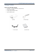
Product Overview
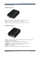
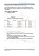
GXV3500 Front Panel
1 V_IN – 1 BNC (Voltage: 1.0V p-p, Resistance 75Ω) port for video input
2 MIC IN – 3.5mm port for audio input devices, ie. Microphones
3 RESET - Press the Reset button for 15 seconds to perform a factory reset.
GXV3500 Back panel
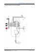
1 DC 12V – 12V DC power port; insert the positive bare wire here (+12VDC), insert the
negative bare wire into the GND port.
2 NETWORK – 10/100 Switch LAN port for connecting to Ethernet.
3 ALARM IN – 1 Alarm Input port for alarm equipment, ie. Infrared detector.
4 ALARM OUT – 1 Alarm Input port for detectors, ie. Sirens.
5 RS-485 – 1 PTZ connector.
6 AV_OUT – 3.5mm to RCA audio/video connection for output to display.