
User's Manual

FIRMWARE VERSION 1.0.0.3 GXP2140 USER MANUAL Page 12 of 77
INSTALLATION
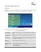
EQUIPMENT PACKAGING
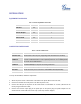
Table 4: GXP2140 EQUIPMENT PACKAGING
Main Case
Yes
1
Handset
Yes
1
Phone Cord
Yes
1
Power Adaptor
Yes
1
Ethernet Cable
Yes
1
Phone Stand
Yes
1
Wall Mount
Yes
1
Quick Start Guide
Yes
1
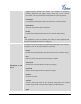
CONNECTING YOUR PHONE
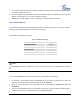
Table 5: GXP2140 CONNECTORS
Handset Port
RJ9 handset connector port
Headset Port
RJ9 headset connector port (supporting EHS with Plantronics headset)
USB Port
USB devices can be connected via the USB port. For example, you can
connect a USB flash drive to save captured pictures or use a USB keyboard
or mouse for the web browser
LAN Port
10/100/1000Mbps RJ-45 port connecting to Ethernet
PC Port
10/100/1000Mbps RJ-45 port connecting to PC
EXT Port
RJ11 connector port to connect the GXP2200EXT Board(GXP2140)
Power Jack
12V DC Power connector port
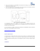
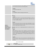
To set up the GXP2140, follow the steps below:
1. Attach the phone stand or wall mount to the back of the phone where there are slots;
2. Connect the handset and main phone case with the phone cord;
3. Connect the LAN port of the phone to the RJ45 socket of a hub/switch or a router (LAN side of the
router) using the Ethernet cable;
4. Connect the 12V DC output plug to the power jack on the phone; plug the power adapter into an
electrical outlet. If PoE switch is used in step 3, this step could be skipped;