
User manual


FIRMWARE VERSION 1.0.5.15 GXP2124 USER MANUAL Page 13 of 71
Table 3: GXP2124 CONNECTORS
Handset Port RJ9 handset connector port
Headset Port RJ9 headset connector port, supporting EHS (Electronic Hook-
Switch) with
Plantronics headsets
LAN Port 10/100/1000Mbps RJ-45 port connecting to Ethernet, integrated PoE
PC Port 10/100/1000Mbps RJ-45 port for PC connection
Power Jack 5V DC Power connector port
To set up the GXP2124, follow the steps below:
1. Attach the phone stand or wall mount to the back of the phone where there are slots;
2. Connect the handset and main phone case with the phone cord;
3. Connect the LAN port of the phone to the RJ-45 socket of a hub/switch or a router (LAN side of the
router) using the Ethernet cable;
4. Connect the 5V DC output plug to the power jack on the phone; plug the power adapter into an
electrical outlet. If PoE switch is used in step 3, this step could be skipped;
5. The LCD will display provisioning or firmware upgrade information. Before continuing, please wait for
the date/time display to show up;
6. Using the keypad configuration menu or phone's embedded web server (Web GUI) by entering the IP
address in web browser, you can further configure the phone.
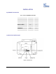
Please see below the pin-out information for GXP2124.
Figure 2: GXP2124 Pin-out
GXP2124 Power Jack
GXP2124 Handset/Headset Jack
GXP2124 Handset/Headset Plug