
User's Manual
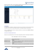
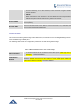
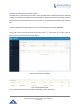
Table Of Contents
- FIRMWARE VERSION 1.0.0.8 9
- TECHNICAL SPECIFICATIONS 11
- EQUIPMENT PACKAGING 13
- CONNECT YOUR GWN7000 13
- SAFETY COMPLIANCES 14
- WARRANTY 14
- LED INDICATORS 15
- USE THE CLI INTERFACE 16
- USE THE WEB GUI 17
- STATUS 21
- WAN PORTS 22
- CONNECTING DEVICES TO LAN PORTS 24
- USER MANAGEMENT 24
- TIME&DATE SETTINGS 25
- DEVICE ROLE(MASTER/SLAVE) 26
- OVERVIEW 27
- GWN7610 ACCESS POINT 错误!未定义书签。
- ZONES 31
- CLIENTS 34
- OVERVIEW 37
- UPGRADING FIRMWARE 39
- PROVISIONING AND BACKUP 40
- RESET AND REBOOT 41
- SYSLOG 41
- DOCUMENT PURPOSE
- CHANGE LOG
- WELCOME
- PRODUCT OVERVIEW
- INSTALLATION
- GETTING STARTED
- ROUTER CONFIGURATION
- SETTING UP A WIRELESS NETWORK
- CLIENTS CONFIGURATION
- VPN
- UPGRADING AND PROVISIONING
- EXPERIENCING THE GWN7000 VPN ROUTER

GWN7000 Enterprise Router & Access Point Manager
User Manual
CONNECT YOUR GWN7610 ACCESS POINT
Figure 15: GWN7610 Ports
Table 7: GWN7610 Ports Description
Port Description
Power Power adapter connector (12V, 2A)
NET/PoE Ethernet RJ45 port (10/100/1000Mbps) supporting PoE.
NET
Ethernet RJ45 port (10/100/1000Mbps) to your router or another GWN7600
series
USB 2.0 port(for future IOT & location based applications)
RESET Factory reset button. Press for 7 seconds to reset factory default settings.
To connect the GWN7610 access point, follow the steps below:
1. Connect one end of an RJ-45 Ethernet cable into the NET or PoE/NET port of the GWN7610.
2. Connect the other end of the Ethernet cable(s) into a LAN port of the the GWN7000 Router
3. Connect the 12V DC power adapter into the power jack on the back of the GWN7610. Insert the
main plug of the power adapter into a surge-protected power outlet.
4. Wait for the GWN7000 to boot up and acquire an IP address from the GWN7000. The above LEDs
of the GWN7610 access point will start flashing in blue.
Page | 28