Grandstream Networks, Inc.
GXP1100/GXP1105 User Manual Index GNU GPL INFORMATION .......................................................................... 5 CHANGE LOG ........................................................................................... 6 FIRMWARE VERSION 1.0.4.23 ............................................................................................................ 6 FIRMWARE VERSION 1.0.4.9 ..............................................................................................................
CONFIGURATION VIA IVR MENU ...................................................................................................... 22 CONFIGURATION VIA WEB BROWSER ........................................................................................... 23 DEFINITIONS ...................................................................................................................................... 24 STATUS PAGE DEFINITIONS ................................................................................
GUI Interface Examples GXP1100/GXP1105 User Manual http://www.grandstream.com/products/gxp_series/general/documents/gxp110x_gui.zip 1. Screenshot of Configuration Login Page 2. Screenshot of Status Page 3. Screenshot of Basic Setting Configuration Page 4. Screenshot of Advanced User Configuration Page 5. Screenshot of SIP Account Configuration Page 6. Screenshot of Saved Configuration Changes Page 7. Screenshot of Reboot Page FIRMWARE VERSION 1.0.4.
GNU GPL INFORMATION GXP1100/GXP1105 firmware contains third-party software licensed under the GNU General Public License (GPL). Grandstream uses software under the specific terms of the GPL. Please see the GNU General Public License (GPL) for the exact terms and conditions of the license. Grandstream GNU GPL related source code can be downloaded from Grandstream web site from: http://www.grandstream.com/support/faq/gnu_gpl. FIRMWARE VERSION 1.0.4.
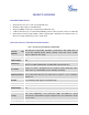
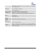
CHANGE LOG This section documents significant changes from previous versions of GXP1100/GXP1105 user manuals. Only major new features or major document updates are listed here. Minor updates for corrections or editing are not documented here. FIRMWARE VERSION 1.0.4.23 • Updated generic config file cfg.xml information. [CONFIGURATION FILE DOWNLOAD] • Added "Use Privacy Header" and "Use P-Preferred-Identity Header" options in web GUI. [ACCOUNT PAGE DEFINITIONS] • Added NAT Settings information.
WELCOME Thank you for purchasing Grandstream GXP1100/GXP1105 Small Business IP Phone. GXP1100/GXP1105 is a next generation small business IP phone that features up to 2 calls with 1 SIP account, 4 programmable keys, single network port, integrated PoE (GXP1105 only).
PRODUCT OVERVIEW FEATURE HIGHTLIGHTS • Single SIP Account, up to 2 calls, 4 programmable keys • HD handset with support for wideband audio • Single 10/100Mbps network port, integrated PoE (GXP1105 only) • 7 dedicated function keys for Hold, Flash/Call Waiting, Transfer, Message, Mute, Volume, Send/Redial • Automated provisioning using TR-069 or AES encrypted XML configuration file, SRTP and TLS for advanced security and privacy protection, LLDP, IPv6 GXP1100/GXP1105 TECHNICAL SPECIFICATIONS Table
Simplified Chinese, traditional Chinese, Korean, Japanese, and etc supported in web configuration interface Upgrade and Firmware upgrade via TFTP/HTTP/HTTPS, mass provisioning using TR-069 or AES encrypted XML configuration file Provisioning Universal power adapter: Power and Green Input: 100-240VAC 50-60Hz; Output: 5VDC, 800mA Energy Efficiency Integrated Power-over-Ethernet (802.3af, GXP1105 only) Typical power consumption under 1W (power adapter) or under 1.
INSTALLATION EQUIPMENT PACKAGING Table 2: GXP1100/GXP1105 EQUIPMENT PACKAGING Main Case Yes (1) Handset Yes (1) Phone Cord Yes (1) Power Adaptor Yes (1) Ethernet Cable Yes (1) Phone Stand Yes (1) Quick Start Guide Yes (1) CONNECTING YOUR PHONE Figure 1: GXP1100/GXP1105 Ports Table 3: GXP1100/GXP1105 CONNECTORS Handset Port RJ9 handset connector port LAN Port 10/100Mbps RJ-45 port connecting to Ethernet, integrated PoE (GXP1105 only) Power Jack 5V DC Power connector port FIRMWARE VERS
To set up the GXP1100/GXP1105, follow the steps below: 1. Attach the phone stand to the back of the phone where there is a slot for the phone stand; 2. Connect the handset and main phone case with the phone cord; 3. Connect the LAN port of the phone to the RJ-45 socket of a hub/switch or a router (LAN side of the router) using the Ethernet cable; 4. Connect the 5V DC output plug to the power jack on the phone; plug the power adapter into an electrical outlet.
USING THE GXP1100/GXP1105 GETTING FAMILAR WITH THE KEYPAD The following table describes the buttons used on the GXP1100/GXP1105 keypad. Table 4: GXP1100/GXP1105 KEYPAD DEFINITIONS Hold. Place active call on hold, or resume the call on hold. Flash. Flash key can be used for multiple purposes. • Call waiting. Bring up a new line; or answer the second incoming call. • 3-way Conference. Establish 3-way conference when FLASH key is configured as CONF.
MAKING PHONE CALLS 2 CALLS WITH 1 SIP ACCOUNT GXP1100/GXP1105 can support up to two lines “virtually” mapped to one SIP account. By picking up the handset, the GXP1100/GXP1105 will be in off hook state and the dial tone will be heard. To make a call, dial out the number with the current line. During the call, users can press the FLASH key to hold the current call and make/answer another call. If they are 2 calls established, users can switch the two lines by pressing the FLASH key.
Note: • After entering the number, the phone waits for the No Key Entry Timeout (Default timeout is 4 seconds, configurable via Web GUI) before dialing out. Press SEND or # key to override the No Key Entry Timeout; • If digits have been entered after handset is off hook, the SEND key will works as SEND instead of REDIAL; • By default, # can be used as SEND to dial the number out. Users could disable it by setting "User # as Dial Key" to "No" from Web GUI->Account page.
To enable Quick IP Call Mode, go to GXP1100/GXP1105 Web GUI->Advanced Setting page, set "Use Quick IP Call Mode" to "Yes". Then take the handset off hook and dial #xxx where x is 0-9 and xxx<255. Press # or SEND and a direct IP call to aaa.bbb.ccc.XXX will be completed. "aaa.bbb.ccc" is from the local IP address regardless of subnet mask. The number #xx or #x are also valid. The leading 0 is not required (but it's OK). For example: • 192.168.0.2 calling 192.168.0.
Note: If users hang up the current call while there is a call on hold in the other line, there will be an audible ring tone indicating a call is on hold while your handset is put on hook. Pick up the handset so users can resume with the call on hold. MUTE During an active call, press the MUTE key to mute/unmute the microphone. CALL TRANSFER GXP1100/GXP1105 supports Blind Transfer, Attended Transfer and Auto-Attended Transfer. • • • Blind Transfer.
Note: • To transfer calls across SIP domains, SIP service providers must support transfer across SIP domains. • In auto-attended transfer, use SEND key to dial out the second call instead of using #, even when # could be used as SEND in normal phone calls. 3-WAY CONFERENCING GXP1100/GXP1105 can host 3-way conference call by using Multi Purpose Key or FLASH key.
will be put on hold separately; Press HOLD key again and it will resume the 2-way conversation with the line when establishing the conference call; Press FLASH key to toggle between the 2 lines; Users could re-establish conference call by pressing the Multi Purpose Key again. 3. End Conference. Press HOLD key to split the conference call. The conference call will be ended with both calls on hold; Or • Users could simply hang up the call to terminate the conference call.
feature "Transfer on Conference Hangup" is turned on. • The option "Disable Conference" has to be set to "No" to establish conference on GXP110x. VOICE MESSAGES (MESSAGE WAITING INDICATOR) A blinking red MWI (Message Waiting Indicator) indicates a message is waiting. Dial into the voicemail box to retrieve the message by entering the voice mail number of the server or pressing the MSG key (Voice Mail User ID has to be properly configured as the voice mail number under Web GUI->Account page).
• Off hook the phone; • Dial *70 and then enter the number to dial out. Enable Call Waiting (per Call) *71 • Off hook the phone; • Dial *71 and then enter the number to dial out. Unconditional Call Forward. To set up unconditional call forward: *72 • Pick up the handset; • Dial *72. A dial tone will be heard; • Enter the forwarding number; • Press # or SEND key; • The call will hang up automatically with unconditional call forward set up. Cancel Unconditional Call Forward.
• Dial *93. A short tone will be heard; • Wait for the call to hang up. The delayed call forward is cancelled. FIRMWARE VERSION 1.0.4.
CONFIGURATION GUIDE The GXP1100/GXP1105 can be configured via two ways: • IVR Menu using the phone's keypad; • Web GUI embedded on the phone using PC's web browser. CONFIGURATION VIA IVR MENU GXP1100/GXP1105 has a built-in voice prompt menu for simple device configuration. Pick up the handset and dial *** to use the IVR menu. Table 6: GXP1100/GXP1105 IVR MENU Menu Main Menu Voice Prompt Options "Enter a Menu Option" Press * for the next menu option. Press # to return to the main menu.
• G-723 • G-729 10 "MAC Address" Announces the MAC address of the unit. 13 "Firmware Server IP Address" Announces current Firmware Server IP address. Enter 12 digit new IP address. 14 15 "Configuration Server IP Announces current Config Server Path IP address. Address" Enter 12 digit new IP address. "Upgrade Protocol" Upgrade Protocol for firmware and configuration update. Enter 9 to toggle between HTTP, TFTP and HTTPS. 16 "Firmware Version" Firmware version information.
4. Open a Web browser on your computer; 5. Enter the phone’s IP address in the address bar of the browser; 6. Enter the administrator’s login and password to access the Web Configuration Menu. Note: • The computer has to be connected to the same sub-network as the phone. This can be easily done by connecting the computer to the same hub or switch as the phone connected to.
IPv4 Address The IPv4 address obtained on the phone. IPv6 Address The IPv6 address obtained on the phone. Product Model Product model of the phone. Part Number Product part number. Software Version • boot: boot version number; • core: core version number; • base: base version number; • prog: program version number. This is the main firmware release number, which is always used for identifying the software system of the phone; • dsp: DSP version number.
ITSP (SIP) server before the account can be registered. After it is saved, this will appear as hidden for security purpose. Name The SIP server subscriber's name (optional) that will be used for Caller ID display. This parameter controls how the Search Appliance looks up IP addresses for hostnames. There are four modes: A Record, SRV, NATPTR/SRV, Use Configured IP. The default setting is "A Record". If the user wishes to locate the server by DNS SRV, the user may select DNS Mode "SRV" or "NATPTR/SRV".
choose from TCP, UDP and TLS. SIP URI Scheme when using Specifies if "sip:" or "sips:" will be used when TLS/TCP is selected for TLS SIP Transport. The default setting is "sips:". Use Actual Ephemeral Port in Contact with TCP/TLS Check Domain Certificates Defines whether the actual ephemeral port in contact with TCP/TLS will be used or not. This is used when TLS/TCP is selected for SIP Transfer. The default setting is "No".
on the phone. This ID is usually the VM portal access number. For example, in Asterisk server, 8500 could be used. Specifies the mechanism to transmit DTMF digits. There are 3 Send DTMF supported modes: in audio which means DTMF is combined in the audio signal (not very reliable with low-bit-rate codecs), via RTP (RFC2833), or via SIP INFO. DTMF Payload Type Early Dial Dial Plan Prefix Configures the payload type for DTMF using RFC2833. The default value is 101.
Example of a simple dial plan used in a Home/Office in the US: { ^1900x. | <=1617>[2-9]xxxxxx | 1[2-9]xx[2-9]xxxxxx | 011[2-9]x. | [3469]11 } Explanation of example rule (reading from left to right): • ^1900x.
Caller Request Timer Callee Request Timer If set to "Yes" and the remote party supports session timers, the phone will use a session timer when it makes outbound calls. If set to "Yes" and the remote party supports session timers, the phone will use a session timer when it receives inbound calls. If Force Timer is set to "Yes", the phone will use the session timer even if Force Timer the remote party does not support this feature.
Selects the distinctive ring tone for the matching rule. When the Distinctive Ringtones incoming caller ID or Alert Info matches the rule, the phone will ring with the selected ring. Defines the timeout (in seconds) for the rings on no answer. The default Ring Timeout setting is 60 seconds. If set to "Yes", the "From" header in outgoing INVITE messages will be Send Anonymous set to anonymous, essentially blocking the Caller ID to be displayed. If set to "Yes", anonymous calls will be rejected.
For end users, it is recommended to use the default setting, as incorrect settings may influence the audio quality. Defines the timeout (in seconds) for no key entry. If no key is pressed No Key Entry Timeout (s) after the timeout, the digits will be sent out. The default value is 4 seconds. Allows users to configure the "#" key as the "Send" key. If set to "Yes", Use # as Dial Key the "#" key will immediately dial out the input digits. In this case, this key is essentially equivalent to the "Send" key.
SETTINGS/BASIC SETTINGS PAGE Allows the administrator to set the password for user-level web GUI End User Password access. This field is case sensitive with a maximum length of 30 characters. Confirm Password Confirms the end user password field to be the same as above. Internet Protocol Selects Prefer IPv4 or Prefer IPv6. Allows users to configure the appropriate network settings on the phone IPv4 Address Type to obtain IPv4 address. Users could select "DHCP", "Static IP" or "PPPoE".
DNS Server 2 Enter the DNS Server 2 for IPv6. Preferred DNS server Enter the Preferred DNS Server for IPv6. Allows the user to enable/disable 802.1x mode on the phone. The 802.1x mode default value is disabled. To enable 802.1x mode, this field should be set to EAP-MD5. Identity Enter the Identity for the 802.1x mode. MD5 Password Enter the MD5 Password for the 802.1x mode. Specifies the HTTP proxy URL for the phone to send packets to.
Default is set to: MTZ+6MDT+5,M4.1.0,M11.1.0 MTZ+6MDT+5 This indicates a time zone with 6 hours offset with 1 hour ahead which is U.S central time. If it is positive (+) if the local time zone is west of the Prime Meridian (A.K.A: International or Greenwich Meridian) and negative (-) if it is east. M4.1.0,M11.1.0 The 1st number indicates Month: 1,2,3.., 12 (for Jan, Feb, .., Dec) The 2nd number indicates the nth iteration of the weekday: (1st Sunday, rd 3 Tuesday…) The 3rd number indicates weekday: 0,1,2,.
default setting is 20 seconds. The NAT IP address used in SIP/SDP messages. This field is blank at Use NAT IP the default settings. It should ONLY be used if it's required by your ITSP. The IP address or Domain name of the STUN server. STUN resolution STUN Server results are displayed in the STATUS page of the Web GUI. Only non-symmetric NAT routers work with STUN.
Enable TR-069 Enables TR-069. The default setting is "No". ACS URL URL for TR-069 Auto Configuration Servers (ACS). TR-069 Username ACS username for TR-069. TR-069 Password ACS password for TR-069. Enables periodic inform. If set to "Yes", device will send inform packets Periodic Inform Enable to the ACS. The default setting is "No". Periodic Inform Interval Connection Request Username Sets up the periodic inform interval to send the inform packets to the ACS.
Allow DHCP Option 42 Override NTP Server Defines whether DHCP Option 42 should override NTP server or not. When enabled, DHCP Option 42 will override the NTP server if it's set up on the LAN. The default setting is "Yes". SSL Certificate SSL Certificate used for SIP Transport in TLS/TCP. SSL Private Key SSL Private key used for SIP Transport in TLS/TCP. SSL Private Key Password SSL Private key password used for SIP Transport in TLS/TCP. System ring tone. Default is North American standard.
The default setting is "No". Disable Transfer Disables the Transfer function. The default setting is "No". If set to "Yes", the phone will use attended transfer by default. The Auto-Attended Transfer default setting is "No". In-call dial number on pressing If configured, the phone will use the TRAN key to dial the number as transfer key DTMF during the call. If configured, when the phone is onhook, it will go offhook after the Offhook timeout timeout (in seconds). The default value is 30 seconds.
CLICK-TO-DIAL From GXP1100/GXP1105 Web GUI, users could dial out with Click-to-Dial feature of the Web GUI when the account is registered. After clicking on the on the top menu icon, a new dialing window will show as the figure below. Enter number and click on "Dial", the phone will go off hook and dial out the number from account 1.
• ip_address: Phone's IP Address. • phonenumber=1234: The number for the phone to dial out • account=0: The account index for the phone to make call. The index is 0 for account 1, 1 for account 2, 2 for account 3, and etc. • password=admin: The admin login password of phone's Web GUI. SAVING THE CONFIGURATION CHANGES After users makes changes to the configuration, press the Update button on the bottom of the Web GUI page. We recommend rebooting or powering cycle the IP phone after saving changes.
UPGRADING AND PROVISIONING The GXP1100/GXP1105 can be upgraded via TFTP/HTTP/HTTPS by configuring the URL/IP Address for the TFTP/HTTP/HTTPS server and selecting a download method. Configure a valid URL for TFTP or HTTP; the server name can be FQDN or IP address. Examples of valid URLs: firmware.grandstream.com fw.ipvideotalk.com/gs There are two ways to setup a software upgrade server: The IVR Menu or the Web Configuration Interface.
The indicator on the top right corner will turn orange and red and then turn off which indicates the phone has restarted. After a while the indicator will blink in red meaning the download is in process. When download is done you will see the phone restarts again. Please do NOT disrupt or power down the unit. If a firmware upgrade fails for any reason (e.g.
CONFIGURATION FILE DOWNLOAD Grandstream SIP Devices can be configured via the Web Interface as well as via a Configuration File (binary or XML) through TFTP or HTTP/HTTPS. The "Config Server Path" is the TFTP or HTTP/HTTPS server path for the configuration file. It needs to be set to a valid URL, either in FQDN or IP address format. The "Config Server Path" can be the same or different from the "Firmware Server Path".
RESTORE FACTORY DEFAULT SETTINGS Warning: Restoring the Factory Default Settings will delete all configuration information on the phone. Please backup or print all the settings before you restore to the factory default settings. Grandstream is not responsible for restoring lost parameters and cannot connect your device to your VoIP service provider. Please follow the instructions below to reset the phone: Pick up the handset, press *** to access the IVR menu. Enter 99 for factory reset.
EXPERIENCING THE GXP1100/GXP1105 Please visit our website: http://www.grandstream.com to receive the most up- to-date updates on firmware releases, additional features, FAQs, documentation and news on new products. We encourage you to browse our product related documentation, FAQs and User and Developer Forum for answers to your general questions. If you have purchased our products through a Grandstream Certified Partner or Reseller, please contact them directly for immediate support.