
Accessories PNEG-914 Manual

5. Installation
PNEG-914 Flex-Flo 21
Auger Tubing Installation (Continued)
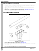
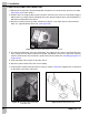
5. Remove the non-belled end of the straight tubing from the “building” elbow. Slide the belled end of
the straight tubing over the freshly cut end of the “unloader” elbow. Mark and cut the straight tubing
(as needed) so that it will fit inside the belled end of the “building” elbow.
6. Dry fit all of the outside tubing to ensure correct installation. Once satisfied, glue or clamp the tubing
together as per the instructions in the section titled cementing procedure on Page 22.
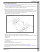
7. When the auger tubing between the unloader and the building is 15' (4.57 m) or longer, the tubes
should be supported.
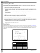
8. Locate and cut the outlet holes needed in the remaining straight tubes. For the exact size of outlet
holes, see section titled outlet holes on Page 22. Once ALL of the outlet holes are made and the
tubing is dry fitted, glue or clamp the tubes together per the instructions in the section entitled
cementing procedure on Page 22.
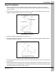
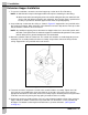
9. Suspend the auger tubes and elbows from the ceiling at least once every four feet (4'). If horizontal
elbows are used, support them in at least two (2) places. Chain and lag screws are provided in each
suspension kit. The tubes should be kept as straight and level as possible.
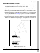
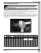
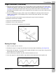
Figure 5K Cutting Chart for 45° Elbow
NOTE: Align all outlet holes in proper functional positions prior to gluing the tube joints together.
5' (1.524 m) Radius
15° Elbow - 15-3/4" (40.005 cm)
45° Elbow - 47-1/4" (120.015 cm)
30° Elbow - 31-1/2" (80.01 cm)
6' (1.829 m) Radius
15° Elbow - 20-3/16" (51.276 cm)
45° Elbow - 60-1/2" (153.67 cm)
30° Elbow - 40-5/16" (102.394 cm)
10' (3.048 m) Radius
15° Elbow - 32" (81.28 cm)
45° Elbow - 96" (243.84 cm)
30° Elbow - 64" (162.56 cm)