Installation and Operation of Flex-Flo Model 220, 300, 350, 500 and HR Installation and Owner’s Manual PNEG-914 Date: 02-04-11 PNEG-914
PNEG-914 Flex-Flo
Table of Contents Contents Chapter 1 Safety .....................................................................................................................................................5 Safety Guidelines ...................................................................................................................................5 General Safety Statement ......................................................................................................................6 Chapter 2 Decals ...
Table of Contents Chapter 7 Wiring Diagrams .................................................................................................................................55 FLX-4496 or FLX-5015 Factory Wiring Diagram ..................................................................................55 Wiring Diagram for Extension Flex-Flo Using Smart-Flex Control .......................................................56 Wiring Diagram for Extension Flex-Flo Using Two (2) FLX-4496 Controls ...............
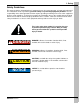
1. Safety Safety Guidelines This manual contains information that is important for you, the owner/operator, to know and understand. This information relates to protecting personal safety and preventing equipment problems. It is the responsibility of the owner/operator to inform anyone operating or working in the area of this equipment of these safety guidelines. To help you recognize this information, we use the symbols that are defined below. Please read the manual and pay attention to these sections.
1. Safety General Safety Statement Our foremost concern is your safety and the safety of others associated with grain handling equipment. This manual is to help you understand safe operating procedures and some problems which may be encountered by the operator and other personnel. As owner and/or operator, you are responsible to know what requirements, hazards and precautions exist and inform all personnel associated with the equipment or in the area. Safety precautions may be required from the personnel.
1. Safety CE Compliance In accordance with European Union Directives, GSI has made every effort to ensure that this product complies with the essential requirements of the machinery directive, the low voltage directive and the electromagnetic compatibility directive. As such, we have declared conformity and affixed the CE mark. Our declaration relates only to genuine GSI Flex-Flo Systems installed as intended by GSI.
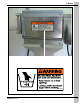
2. Decals THE GSI GROUP FLX-4512 ELECTRICAL BOX ASSEMBLY CONTACT RATING: 1-1/2 HP @ 240 VAC MAX., 25 FLA, 1 PHASE COIL RATING: 208-240 VAC, 50/60 Hz. DC-1238 DANGER High Voltage. Will cause injury or death. Lockout power before servicing. THE GSI GROUP FLX-4512-3 ELECTRICAL BOX ASSEMBLY CONTACT RATING: 1-1/2 HP @ 240 VAC MAX., 25 FLA, 3 PHASE COIL RATING: 280-240 VAC, 50/60 Hz. DC-1238-2-3 DANGER High Voltage. Will cause injury or death. Lockout power before servicing.
2.
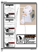
3. Introduction Applications In poultry application, Flex-Flo Fill System conveys feed from bulk feed tank to hoppers inside the poultry building as shown in Figure 3A. Other feed systems (i.e. cycle plus, chain feeder etc.) take the feed from the hopper to the desired locations in the building. On this layout, hopper level switches may be placed in more than one hopper to assure that no hopper empties before the control unit hopper requires feed.
4. Flex-Flo Specifications (English/Metric) Flex-Flo Systems Specifications Model 220 Model 300 Model 350 Model 500 Model HR Auger Tube Diameter 2.2" 55 mm 3" 75 mm 3-1/2" 90 mm 5" 125 mm 3-1/2" 90 mm Carrying Capacity based on 40 lbs./cubic ft. 15 lbs./min 7 kg/min 900 lbs./hr 420 kg/hr 50 lbs./min 22 kg/min 3000 lbs./hr 1400 kg/hr 100 lbs./min 45 kg/min 6000 lbs./hr 2700 kg/hr 220 lbs./min 100 kg/min 13200 lbs./hr 6000 kg/hr 50 lbs./min 22 kg/min 3000 lbs.
4. Flex-Flo Specifications (English/Metric) Tank Centerline to Building Entrance Distance “X” from Given Height “H” (English) Model 220 with 10' Radius Elbows “X” for 30° Boot (ft.) “X” for Straight Boot (ft.) “H” (ft.) 30° 45° 60° 30° 45° 5.0 10.5 - - 15.0 - 60° - 6.0 12.5 11.0 - 17.0 - - 7.0 14.0 12.0 - 18.5 17.0 - 8.0 16.0 13.0 - 20.0 18.0 - 9.0 17.5 14.0 - 22.0 19.0 - 10.0 19.5 15.0 - 23.5 20.0 - 11.0 21.0 16.0 14.5 25.5 21.0 19.5 12.0 23.0 17.
4. Flex-Flo Specifications (English/Metric) Figure 4D Equipment Orientation Charts Tank Centerline to Building Entrance Distance “X” from Given Height “H” (Metric) Model 220 with 10' Radius Elbows “X” for 30° Boot (m) “X” for Straight Boot (m) “H” (m) 1.52 1.83 2.13 2.44 2.74 3.05 3.35 3.66 3.96 4.27 4.57 4.88 5.18 5.49 5.79 6.10 30° 45° 60° 30° 45° 60° 3.20 3.81 4.27 4.88 5.33 5.94 6.40 7.01 7.47 8.08 8.53 9.14 9.60 10.21 10.67 11.28 3.35 3.66 3.96 4.27 4.57 4.88 5.18 5.49 5.79 6.10 6.40 6.
4. Flex-Flo Specifications (English/Metric) Model 220, 300, 350 and HR with 5' Radius Elbow “X” for 30° Boot (m) “X” for Straight Boot (m) “H” (m) 30° 45° 60° 30° 45° 60° 1.52 2.74 - - 3.66 3.05 - 1.83 3.20 2.44 2.29 4.11 3.35 3.05 2.13 3.66 2.74 2.44 4.72 3.66 3.35 2.44 4.27 3.05 2.59 5.18 3.96 3.51 2.74 4.72 3.35 2.74 5.64 4.27 3.66 3.05 5.18 3.66 2.90 6.25 4.57 3.81 3.35 5.79 3.96 3.05 6.71 4.88 3.96 3.66 6.25 4.27 3.35 7.32 5.18 4.11 3.
5. Installation CAUTION Improper installation methods of the hardware may cause permanent damage and possible breakage of the boot. Boot and Transfer Plate Installation NOTE: Installation of the boot is the same whether the tank has the standard collar or the Sure-Flo Feed Flow Control. Slide the boot as far as possible into the tank collar or the Sure-Flo Feed Flow Control opening. (See Figure 5A.) Align the boot with the Flex-Flo System that will be installed.
5. Installation Slide Gate Installation Insert the slide into the transfer plate. The slide must be in its operating position prior to attaching the slide shield to the transfer plate. Use two (2) 5/16"-18 x 1" truss head tap bolts to mount the slide shield. (See Figure 5D.) Bolt unloader to transfer plate/unloader brace assembly as shown in Figure 5E. Note orientation of these bolts. (See Figure 5E.
5. Installation Inspection/Clean-Out Plate Installation Once the installation of the auger tubes and auger is complete, insert the inspection/clean-out plate or the optional unloader switch. The inspection/clean-out plate is to be installed per the following instructions: (See Figure 5F.) 1. Back off both wing nuts to the stud ends. 2. Slide the plate onto the lower side of the unloader opening. 3. Move the plate first against the side of the unloader then upward toward the top of the unloader. 4.
5. Installation Feed Tank Collar The standard bulk feed tank is supplied with a 16'' (40.64 cm) hopper opening. If needed, 22'' (55.88 cm) hopper openings are also available. Consult the dealer for specific ordering instructions. Restrictor Adjustment The restrictor may be adjusted to allow more feed flow. Do not modify the restrictor until the system is completely operational and the auger has been polished by running feed through the system. Instructions: 1. Remove the restrictor tube from the unloader.
5. Installation Straight-Through Tandem Installation The straight-through tandem system should be installed the same as a single tank system with the following exceptions: 1. Mount the boots on both tanks and the single or twin-out unloader as instructed. 2. Install baffle plate (FLX-4310) in the single-through unloader as shown in Figure 5H. The twin unloader baffle is factory installed as shown in Figure 5H. Figure 5H 3.
5. Installation Auger Tubing Auger Tubing Installation The auger tubing is one of the most important parts of the Flex-Flo Fill System. Proper installation is very important. Dry fit ALL parts before cementing or clamping. Once the complete system is fitting properly, cement or clamp the entire system. The following steps are to be performed in the exact order shown: 1. Establish the entry point where the auger tube will enter the building.
5. Installation Auger Tubing Installation (Continued) 5. Remove the non-belled end of the straight tubing from the “building” elbow. Slide the belled end of the straight tubing over the freshly cut end of the “unloader” elbow. Mark and cut the straight tubing (as needed) so that it will fit inside the belled end of the “building” elbow. 6. Dry fit all of the outside tubing to ensure correct installation.
5. Installation Cementing Procedure Flex-Flo Systems have specially formulated PVC tubing. For strong tube connections, apply the PVC solvent cement per the instructions as follows: 1. Square tube ends and remove all burrs and dirt. 2. Check dry fit of tubes. The smaller end of the first tube should easily slide one-third of the way into the belled end of the second tube. The first tube end should be snug in the second tube once it is all the way in. 3.
5. Installation Drop Kit Installation 1. Wrap the rotary slide over the outlet hole and around the auger tube. Position the slides with cut-out facing in the same direction for all drops so that the slides will operate the same when the ropes are pulled. 2. Thread the rope through the ends of the rotary slide as shown in Figure 5M and tie the slide ends together so that the ends of the rope are the same length. Figure 5M Drop Kit Installation 3. Slide rope through molded guide holes in drop halves. 4.
5. Installation Drop Kit Installation (Continued) 7. Thread the short rope end through the red ball and tie a knot in the rope to hold the ball in place. Install the green ball the same way on the other rope end. 8. Apply a small amount of PVC cement around the drop to prevent it from moving around on the auger tube. 9. Two (2) screws are supplied for attaching an optional drop tube. (See Figure 5N on Page 23.) Use both screws to attach the drop tube securely to the drop kit.
5. Installation Power Unit and Control Unit The safety switch on the control unit is provided as a backup switch in case the hopper level or the drop tube switch does not operate properly. This switch is CAUTION not intended to be used for controlling the Flex-Flo System, but as a safety backup switch only. Flex-Flo offers two (2) different types of power units, direct drive unit and belt drive power unit, along with the control unit. Installation instructions are provided with each power unit.
5. Installation Direct Drive Power Unit/Control Unit 1. Bolt the tube anchor to the control unit body with a flat washer on each of the four (4) 5/16'' x 3/4" bolts. (See Figure 5Q for more details.) 2. Slide the driver assembly onto the power unit drive shaft. Place the 5/16" hex socket bolt (supplied with the driver assembly) into the untapped hole of the driver through the drive shaft and tighten the bolt into threaded portion of the driver. 3.
5. Installation Belt Drive Power/Control Unit 1. Bolt the tube anchor to the control unit body with a flat washer on each of the four (4) 5/16'' x 3/4'' bolts. (See Figure 5Q on Page 26 for more details.) 2. Insert the driver shaft through the bearing assembly. The bearing mounting plate should be mounted in between. Tighten the set screw on the bearing down to the shaft. 3. Bolt the two (2) mounting brackets together with the four (4) bolts and washers provided. 4.
5. Installation Auger The auger should be handled with great care. Do not install the auger until the kinks have been removed. The kink may be removed by straightening the auger. A kink may cause extensive wear on the system and premature part replacement. In the event that the kink cannot be removed by straightening, the kink must be cut-out and the auger welded. (See brazing recommendations in Figure 5X on Page 29.) Figure 5U Auger Installation Two (2) persons are required to install the auger.
5. Installation Auger Installation (Continued) 7. Draw the auger out of the tubing as far as required. Measure the length between the mark and the unloader inlet. Mark the auger again at the unloader inlet when properly stretched. (See Figure 5V on Page 28.) Stretching the auger too far will cause premature wear at the inside bends of the PVC tubing. Stretching the auger not far enough will cause premature wear at the outside bends of the PVC tubing. 8.
5. Installation Extension Hopper Installation 1. To ease the installation, mount the extension hopper top section to the Flex-Flo tubing. NOTE: A. Slide the tube clamp on the hopper tube anchor prior to attaching it to the tubing. B. Make certain when mounting the power unit and the tubing that they are attached to the access slide side. When mounted in this orientation, the incoming auger is positioned as far away as possible to allow the upper control switch to operate properly. 2.
5. Installation Extension Hopper Installation (Continued) Figure 5Z Extension Mounting Directions Figure 5AA Extension System 6. Install the auger for the system that is connected from the tank(s) to the extension hopper. Install as a standard system. The auger for the second part of the system should connect to the power/control unit at the other end. 7. Clamp the auger ends to their applicable anchors and mount the bearing assemblies in place.
5. Installation 8. The extension unit switch should actuate prior to “bottoming out” when pressed in and return back to its original position after it is released. Figure 5AB Operation Guidelines 1. Open the unloader slide completely for the delivery system operation except on tandem system. 2. Do not operate the Flex-Flo System empty. Utilize a time clock with the system whenever possible because: A. It lessens short cycling by operating on a set schedule versus on demand. B.
5. Installation 8. When a multi-story building is supplied by one auger solely, obtain total drop-out at each outlet. A time clock MUST be utilized to ensure that all of the feeders are filled at the same time. In the last hopper on every level, install a hopper level control. 9. With the straight-through tandem system, open only one tank slide at a time when feeding. Operating the system with both unloader slides open is not recommended since horsepower consumption increases considerably.
NOTES 34 PNEG-914 Flex-Flo
6. Parts List 1. Flex-Flo Feed Line Components 2. Direct Drive Power Unit Assemblies 3. Model 220 Unloader and Anchor Assembly 4. Model 300, 350 and HR Unloader and Anchor Assembly 5. Model 500 Unloader and Anchor Assembly 6. Direct Drive and Tube Anchor 7. Belt Drive and Tube Anchor 8. Model 220, 300 and 350 Control Unit (FLX-4496) 9. Flex-Flo Control Unit (FLX-5015) 10. Belt Drive Power Unit 11. Direct Drive Power Unit 12. Drop Kit/Kwik-Attach Drop Kit 13. Unloader Switch 14.
6.
6.
6.
6.
6.
6.
6.
6. Parts List Direct Drive and Tube Anchor Ref # Part # Description FLX-2699 220 D.D. Driver and Tube Anchor FLX-2696 300 D.D. Driver and Tube Anchor FLX-2697 350 D.D. Driver and Tube Anchor FLX-2698 500 D.D.
6.
6. Parts List Belt Drive and Tube Anchor Parts List Ref # Part # Description FLX-2695 220 B.D. Driver and Tube Anchor FLX-2692 300 B.D. Driver and Tube Anchor FLX-2693 350 B.D. Driver and Tube Anchor FLX-2694 500 B.D.
6.
6.
6.
6.
6. Parts List Belt Drive Power Unit Ref # Description FLX-4179 14'' Belt Drive Power Unit (Less Motor) FLX-2986 Belt Guard Cover 2 S-4307 5/8" I.D. Locking Collar 3 S-7149 Bolt, HHTB 5/16"-18 x 1-3/4" ZN Grade 5 4 S-6242 2.
6.
6.
6. Parts List Unloader Switch Ref # Part # Description Qty 1 FLX-4157A Back Plate, Unloader Switch Assembly 1 2 FLX-4410 Diaphragm Assembly 1 3 FLX-2380 Small Diaphragm Retainer 1 4 S-849 Hex Nut 10-24 Grade 2 1 5 FLX-4158A Cover Plate Assembly for Switch 1 6 S-3558 3/8" Washer EPDM Steel Backed 1 7 S-4301 Wing Nut 5/16"-18 ZN Grade 2 1 8 FLX-4159 Unloader Switch Housing 1 9 S-3674 Flat Washer #10 x 7/32" I.D. x 1/2" O.D.
6. Parts List Micro Drop Tube Switch/Proximity Switch Micro Drop Tube Switch Parts List Ref # Part # Description Qty AP-0990 Plastic Drop Tube Switch, 110/220V 1 FLX-3489 Micro Switch Box Assembly Wired N.C. 1 2 S-7621 Screw, SDS #10-16 x 1" HWH ZN Grade 2 6 3 FLX-3448 Drop Tube Switch Baffle Plate 1 4 FLX-3451 Drilled Drop Tube Housing 1 Proximity Switch Parts List Ref # 54 Part # Description Qty 1 FLX-2425 Drop Tube, 3" I.D. x 12' (3.
7.
7.
7.
7.
7.
7.
7.
7.
8. Warranty GSI Group, LLC Limited Warranty The GSI Group, LLC (“GSI”) warrants products which it manufactures to be free of defects in materials and workmanship under normal usage and conditions for a period of 12 months after sale to the original end-user or if a foreign sale, 14 months from arrival at port of discharge, whichever is earlier.
This equipment shall be installed in accordance with the current installation codes and applicable regulations which should be carefully followed in all cases. Authorities having jurisdiction should be consulted before installations are made. 1004 E. Illinois St. Assumption, IL 62510-0020 Phone: 1-217-226-4421 Fax: 1-217-226-4420 www.gsiag.