BIN STAIRS & PLATFORM ASSEMBLY ASSEMBLY MANUAL Owner’s Manual Manual # PNEG-780 5-17-07 PNEG-780
Bin Stairs and Platform Assembly 2
Bin Stairs and Platform Assembly Table of Contents Table of Contents Safety First..............................................................................................3 Positioning Stairs and Platform..........................................................4 Platform Assembly.....................................................................5 Stair- Top Section Assembly............................................................6-8 Step Preassembly...............................................
Safety First Bin Stairs and Platform Assembly SAFETY FIRST General Safety Statements The GSI Group Inc’s Principal concern is your safety and the safety of others associated with grain handling equipment. We want to keep you as a customer. This manual is to help you understand safe operating procedures and some problems which may be encountered by the operator and other personnel.
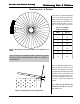
Bin Stairs and Platform Assembly Positioning Stair & Platform Positioning Stairs & Platform Position the roof ladder and manhole to allow for platform placement. Refer to the table on this page to determine where stairs will end. Position the end of the stairs to avoid augers, doors, fans, and control boxes. Spaces around Bin 4.00” Corrugation Figure 1: Orientation of Platform in relation to the manhole & roof ladder.
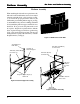
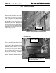
Bin Stairs and Platform Assembly Platform Assembly Platform Assembly When attaching the sidewall access platform to the tank wall, vertical wall brackets need to be mounted to the bin wall with 5/16” x 3/4” bin bolts (see Fig. 3). To insure the proper placement of the second wall bracket, preassemble platform support (see Fig. 4) and mark the hole positions for drilling. Field drill and assemble the platform support with 5/16” truss head bolts. Now, proceed to the platform floor and floor splice.
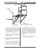
Bin Stairs and Platform Assembly Stair - Top Section Assembly Stair - Top Section Assembly LDR-4092 Wall Bracket (I) LDR-4082 Stair Wall Bracket (II)LDR-4083 Horizontal Bar Bracket LDR-4142 Diagonal Support Angle (III) LDR-4084 Knee Brace I. The stair wall bracket (LDR-4082) should be placed on a horizontal seam and bolted vertically. The vertical location must be field drilled to match up with platform location. Use 5/16” x 1 1/4” bolt to secure LDR-4082 to the sidewall.
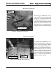
Stair Top Section Assembly Bin Stairs and Platform Assembly Tie Strap Attachment Attach the steps to each other with the tie straps (LDR4090). Use 5/16 x 3/4” truss head bolts and nuts to attach the strap to the holes provided on the ends of the step. Align the step slots and level the steps before tightening. The steps will align to curvature and wall brackets. When all the parts of the top section are in place tighten all the bolts.
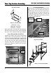
Bin Stairs and Platform Assembly Stair - Top Section Assembly Handrail Post Attachment Handrail Post (LDR-4085) The handrail post (LDR-4085) connects to the end of the horizontal wall bracket with (2) 3/8” x 1” Flange head bolts and nuts. Tighten the bolts and move on to the next section. The handrail will be installed after all stair sections are on the tank. (See figure 10 on page 7 for a detailed drawing of the first few steps and the hand railing.) (2) 3/8” x 1” Flange head bolts and nuts.
4.00” Standard Section Bin Stairs and Platform Assembly 4.00” Standard Section Continue raising the bin until the next wall bracket can be attached to the wall 3 spaces (2.66” Corrugation) or 4 spaces (4.00” Corrugation) along the horizontal seam. Bolt the rest of the assembly in place and field drill to secure. Place a step over the wall bracket and secure. Hang the three steps between brackets to finish the section. Align steps level with tie straps and tighten section.
Handrail Installation Bin Stairs and Platform Assembly Handrail Installation 5/16” x 1 1/4” Bolt and Nut Top Handrail Installation Start at the top handrail post and align the bottom slot with the second post, mark top post location. Trim off the narrow end and drill for top connection. Connect with 5/16” x 1 1/4” bolt and nut. Slide the next narrow end into the upper wide end of the next rail. Align the slots and attach to post with 5/16” x 1 1/4” bolt. Note: Keep post plumb as you tighten the bolt.
Bin Stairs and Platform Assembly NOTES 12
Bin Stairs and Platform Assembly Warranty The GSI Group, Inc. Warranty THE GSI GROUP, INC. (“GSI”) WARRANTS ALL PRODUCTS WHICH IT MANUFACTURES TO BE FREE OF DEFECTS IN MATERIAL AND WORKMANSHIP UNDER NORMAL USAGE AND CONDITIONS FOR A PERIOD OF 12 MONTHS AFTER RETAIL SALE TO THE ORIGINAL END USER. THE PURCHASER’S SOLE REMEDY AND GSI’S ONLY OBLIGATION SHALL BE TO REPAIR OR REPLACE, AT GSI’S OPTION AND EXPENSE, PRODUCTS THAT, IN GSI’S SOLE JUDGMENT, CONTAIN A MATERIAL DEFECT DUE TO MATERIALS OR WORKMANSHIP.
1004 E. Illinois St. P.O. Box 20 Assumption, Il. 62510-0020 Phone: 217.226.4421 Fax: 217.226.4420 e-mail: gsi@grainsystems.com internet: http://www.grainsystems.