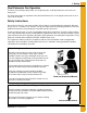
Roof Exhaust Fan Installation and Operation Owner’s Manual PNEG-524 Date: 12-12-12 PNEG-524
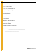
Check List 1. All wire connections 2. Tip clearance on blade 3. Fan blade torqued to torque specs 4. Grill guard in place and tight 5. Motor rotation correct 6. Running amperage 7. Vibration 8. All fasteners tight 9. Indicator light 10. All decals and serial number tag 11. Aesthetic appearance 12. Manual in control box 13.
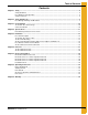
Table of Contents Contents Chapter 1 Safety .....................................................................................................................................................4 Safety Guidelines .................................................................................................................................. 4 Roof Exhauster Fan Operation ............................................................................................................. 5 Safety Instructions ....
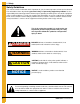
1. Safety Safety Guidelines This manual contains information that is important for you, the owner/operator, to know and understand. This information relates to protecting personal safety and preventing equipment problems. It is the responsibility of the owner/operator to inform anyone operating or working in the area of this equipment of these safety guidelines. To help you recognize this information, we use the symbols that are defined below. Please read the manual and pay attention to these sections.
1. Safety Roof Exhauster Fan Operation Thank you for choosing a GSI product. It is designed to give excellent performance and service for many years. This manual describes the operation of the GSI Roof Exhaust Fan. It is designed to take in bin air and expel it to the outside. Safety Instructions Our foremost concern is your safety and the safety of others associated with this equipment. We want to keep you as a customer.
1. Safety Prepare for Emergencies Be prepared if fire starts. Keep a first aid kit and fire extinguisher handy. Keep emergency numbers for doctors, ambulance service, hospital, and fire department near your telephone. Keep Emergency Equipment Quickly Accessible Wear Protective Clothing Wear close-fitting clothing and safety equipment appropriate to the job. Eye Protection Remove all jewelry. Tie long hair up and back. Gloves Wear safety glasses at all times to protect eyes from debris.
2. Safety Alert Decals The GSI Group recommends contacting the local power company and having a representative survey the installation so the wiring is compatible with their system and adequate power is supplied to the unit. Safety decals should be read and understood by all people in the grain handling area. If a decal is damaged or missing, contact: GSI Decals 1004 E. Illinois St. Assumption, IL. 62510 Phone: 1-217-226-4421 A free replacement will be sent to you.
2. Safety Alert Decals Please remember, safety signs provide important safety information for people working near equipment that is in operation. If the safety sign cannot be easily read for any reason, replace it immediately. Additional safety signs may be obtained from your dealer, distributor or ordered from the factory. GSI Decals 1004 E. Illinois St. Assumption, IL. 62510 Phone: 1-217-226-4421 NOTE: Decals are not shown actual size. WARNING Flame and pressure beyond door can cause serious injury.
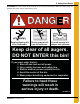
2. Safety Alert Decals ATTENTION: The decal shown below should be present on the outside of the door cover of the 2 ring, 24" porthole door cover and the roof manway cover. Rotating flighting will kill or dismember. Flowing material will trap and suffocate. Crusted material will collapse and suffocate. Keep clear of all augers. DO NOT ENTER this bin! If you must enter the bin: 1. Shut off and lock out all power. 2. Use a safety harness and safety line. 3. Station another person outside the bin. 4.
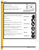
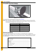
3. Pre-Installation 18" and 24" Roof Fan Package Figure 3A An 18" Roof Exhaust Fan The model package should contain items shown in the Chart below. NOTE: Before starting the assembly and installation of the roof exhaust fan, check to see that all items listed on the packing slip have been received. In case of any shortages, contact the dealer. If there is any damage from shipment, file a claim with the carrier.
4. Specifications Fan Model Specifications for Roof Fans 24" Roof Exhauster Motor Specifications Exhauster Model Fan Sub-Assembly Motor Part # HP Phase Voltage Enclosure RPM Full Load Amps MIS-6675-1 MIS-6674-1 MIS-6729 2 1 230 TEFC 1725 11.5 MIS-6675-3 MIS-6674-3 MIS-6686 2 3 208-230/460 TEFC 1740 6-5.6/2.8 MIS-6675-3E MIS-6674-3E MIS-6704 2 3 230/460 XPFC 1740 5.6/2.8 MIS-6675-5 MIS-6674-5 MIS-6800 2 3 575 TEFC 1740 2.
5. Installation All single phase motors and the 1/2 HP explosion-proof 3 phase motor are supplied with automatic overload protection. The remaining 3 phase motors do not have internal motor protection. Motors rated as explosion-proof (EX PRF) meet class II group F and G of the National Electric Code (NEC). Figure 5A Open area dimensions and 18" 1/2 HP roof fan exhauster side view illustration. Figure 5B Open area dimensions and 24" 2 HP roof fan exhauster side view illustration.
5. Installation 18" and 24" Roof Fan Location The roof fans should be equally spaced on the bin roof circumference. When installed, the roof fan should be positioned as far up the roof slope as the tapered ribs of the bin roof sheet will allow. The roof fan location should be selected to provide a rigid mounting for the fan. For bins with an inner roof structure, the roof fan should be anchored to the inner roof structure.
5. Installation 18" Roof Fan Mounting (Continued) Figure 5D The 18" roof exhauster fan in relation to the roof sheet. 24" Roof Fan Mounting and Assembly of Fan, Adaptor and Rainhood The roof fans, adaptor and rainhood can be installed in the bin roof sheet before assembling the roof or after the roof is assembled. The fan is secured by bolts that must be fastened from the inside of the bin roof, so the assembly should be made before the sidewalls are erected. 1.
5. Installation 24" Roof Fan Mounting and Assembly of Fan, Adaptor and Rainhood (Continued) Figure 5F 24" Roof fan adaptor and template parts breakdown. 2. Place the roof sheet adaptor mounting template at the appropriate location for the roof fan. Move the template as far up the roof sheet as possible, but allow for 1" minimum clearance between the roof sheet rib and bottom of the template on each side. 3. Drill two (2) corner holes and bolt template in place. 4.
5. Installation 24" Roof Fan Mounting and Assembly of Fan, Adaptor and Rainhood (Continued) 5. Mark a cutting line 3/4" inside the template. Then remove template. Drill through the mark, cutting a hole in the roof sheet. (See Figure 5H.) 6. Pre-assemble the adaptor section parts of the roof fan. Loosely bolt the adaptor left side and right side to adaptor top. On all components, bolts are to be installed with the head on the fan housing exterior. 7.
5. Installation 24" Roof Fan Mounting and Assembly of Fan, Adaptor and Rainhood (Continued) Figure 5J The 24" Roof Fan Exhauster and Rainhood 12. Pre-assemble the optional 90° deflector. 13. Bolt deflector assembly to sub-assembly (MIS-6674) for noise deflection. (See Figure 5K.) Figure 5K The 24" Roof Fan Exhauster with Optional 90° Deflector 14. Bolt rainhood to fan housing or optional 90° deflector if installed. 15.
5. Installation 24" Roof Fan Mounting and Assembly of Fan, Adaptor and Rainhood (Continued) 16. The roof fan location should be selected to provide a rigid mounting for the fan. For bins with an inner roof structure, the roof fan should be anchored to the inner roof structure. 17. The fan housing top plate is provided for access to the motor for electrical installation and a knock out is provided in the fan side for the wire access.
5. Installation 24" Roof Exhauster Reinforcement Kit Figure 5M 24" Roof Exhauster Reinforcement Kit Detail (MIS-6804) 1. Refer to Page 16 for the 24" roof adaptor template and mounting and the 30° roof manual PNEG-030 for the roof channel assembly. 2. Install the roof support channels in the ribs of the upper panel where the exhauster is to be mounted. 3. Install the template and cut exhauster parts as specified on Page 16. 4.
NOTES 20 PNEG-524 Roof Exhaust Fan
6.
6.
6.
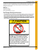
7. Electrical Installation Electrical Installation of the Fan The electrical installation must be performed by a certified electrician in accordance with the appropriate national and local electrical codes. Any violation of electrical wiring codes could jeopardize the airstream warranty. CAUTION Check the type of electrical service present and make sure the fan to be wired is manufactured to operate on the electrical service.
7. Electrical Installation Fan Disconnect A disconnect for the fan needs to be sized to handle the recommended fusetron size. Example: For a 24" fan the first chart on Page 23 would be used and the fusetron size is 30 Amp. Install the fusetron recommended in the disconnect. A circuit breaker can be used, however, the circuit breaker or any fuse used must be a time delay type to allow the initial starting inrush current to the fan.
7. Electrical Installation 3 Phase System With the power OFF at the fan disconnect, exchange the location of the current carrying conductors at terminal L1 and L3 (See Figure 7A) of the magnetic controls. The unit will then need to be re-checked for proper rotation. Figure 7A Correcting the Fan Rotation for 3 Phase Always check current local, state and national codes on electrical requirements before installing any electrical equipment. Transformer size is based on the current draw from the fan only.
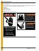
8. Operating Instructions Before Starting Fan When starting the fan for the first time, check the following: 1. With the power OFF, rotate the fan blade to make sure it revolves easily and does not rub on the venturi or fan tube. 2. Check all the fasteners to make sure they are tight. If any are loose, check for proper clearance and retighten. 3. With the power OFF, check all electrical connections to make sure they are tight. Inspect the current carrying wires to make sure they are not grounded.
8. Operating Instructions If the fan just hums when turned ON, check the following: 1. Check to make sure that all leads of the power source have voltage present. If fan unit is not receiving power on all leads, check for a blown fuse, broken wire or loose connection. 2. Check to see that all contact sets are closing. If one leg of the supply voltage is not available to the motor, it will hum. 3.
9. Warranty GSI Group, LLC Limited Warranty The GSI Group, LLC (“GSI”) warrants products which it manufactures to be free of defects in materials and workmanship under normal usage and conditions for a period of 12 months after sale to the original end-user or if a foreign sale, 14 months from arrival at port of discharge, whichever is earlier.
This equipment shall be installed in accordance with the current installation codes and applicable regulations which should be carefully followed in all cases. Authorities having jurisdiction should be consulted before installations are made. GSI Group 1004 E. Illinois St. Assumption, IL 62510-0020 Phone: 1-217-226-4421 Fax: 1-217-226-4420 www.gsiag.