Concrete Foundation Recommendations for GSI Grain Bins Instructions Manual PNEG-318 Date: 06-27-13 PNEG-318
• “FCDL” Series bins • 4.00" (“W”) Series farm bins • 2.
Table of Contents Contents Chapter 1 Introduction ..........................................................................................................................................5 Chapter 2 General Foundation Requirements for GSI Bins ...............................................................................8 Requirements ........................................................................................................................................ 8 Selecting the Proper Site .......
Table of Contents Chapter 16 WC Series Outside Universal Stiffened Anchor Bolt Charts ......................................................114 WC Series Outside Universal Stiffened Anchor Bolt Charts 4" Corrugation Commercial Tanks ..... 114 Chapter 17 Concrete Foundation Commercial Hopper Tanks .......................................................................124 12' Diameter Commercial Hopper Tank Foundation up to 12 Rings ...............................................
1. Introduction ATTENTION: READ BEFORE USING THIS MANUAL All instructions should be construed as recommendations only. Because actual installation will vary according to local conditions, The GSI Group, Inc. assumes no liability for the results arising from the use of such recommendations. Always make sure to use the correct tables and charts for the bin and soil conditions at building site. Determine the following before using this manual: Bin Style 1. FCDL Series 2. “W” Series farm bin (4.
1. Introduction Reinforcement Bar Properties Standard Nominal Dimensions Bar Designation Number Weight per Foot (lb.) 3 Diameter in. (mm.) Cross Sectional Area (sq. in.) 0.367 3/8" (9) 0.110 4 0.668 1/2" (13) 0.200 5 1.043 1-5/8" (16) 0.310 6 1.502 3/4" (19) 0.440 7 2.044 7/8" (22) 0.600 8 2.670 1" (25) 0.790 NOTES: Lap all circumferential bars 35 diameters and stagger all laps in plan 3' 0". All reinforcement bar estimates do not include end laps.
Section 02 ® General Foundation Requirements for GSI Bins PNEG-318 Concrete Foundation Recommendations for GSI Grain Bins 7
2. General Foundation Requirements for GSI Bins Requirements The following construction related notes pertain to the installation of farm bin foundations. Selecting the Proper Site The selected site should be level, firm and free from underlying debris. The bin can be installed satisfactorily on slopes, but as the slope increases, additional labor and materials are required for the foundation. The concrete foundation surface must be level.
2. General Foundation Requirements for GSI Bins Prepare the Foundation Forms After scribing the diameter of the foundation, proceed by digging the foundation’s footing. This consists of a large circular trench dug just inside the foundation line. (Refer to foundation details (frost free pad, inverted “T” and T-Cap) of corresponding bins and tanks in this manual for necessary information.) Once the footing has been dug, you are ready to build the forms.
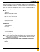
2. General Foundation Requirements for GSI Bins Figure 2C Alternate Foundation Form Place the Reinforcement Once the forms and trench have been prepared, begin the placement of reinforcement rods at various levels in the foundation’s footing. See the appropriate charts and drawings in this manual for the bin to determine requirements and positions of the reinforcement. The reinforcement rods offer their greatest strength when lapped properly and connected by wiring or welding.
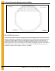
2. General Foundation Requirements for GSI Bins Vane Axial Fan Pad Placement of the Fan Pad: Transitions/Fans/Heaters Only. If a fan or fan and heater will be installed, refer to Figure 2D to determine the concrete pad size. 1. The top of this pad should be level with the top of the bin’s foundation. 2. Recommended pad thickness is 4" minimum. 3. Front of pad should be perpendicular to bin wall. 4. Pad for heater not required, but if it is to added, pour the pad to cover both locations.
2. General Foundation Requirements for GSI Bins Centrifugal Fan Pad 1. Fan pad should be poured 2" below the top of the bin foundation for all centrifugal fans. 2. A pad for heaters is not required, but is recommended. 3. Recommended pad thickness is 4". 4. If a downwind heater pad is to be installed, the pad width (“C”) should be 48" and extended toward the bin by 33". 5. Fan discharge should be centered on centerline of bin. 6. The fan pad should be perpendicular to bin wall.
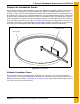
2. General Foundation Requirements for GSI Bins Anchor Bolt Placement Having poured and leveled the concrete, use the center stake and straight 2 x 4 again to find the bolt circle radius for the outside hold-down brackets. Select a starting point and stretch a pre-measured chord along the imaginary circle formed by the bolt circle radius. Take into consideration the placement of these bolts so as not to interfere with the positions of bin doors and transitions.
2. General Foundation Requirements for GSI Bins FCDL Anchor Bolt Detail Figure 2G FCDL Anchor Bolt Detail Commercial Tank Anchor Bolt Detail Figure 2H Commercial Tank Anchor Bolt Detail NOTE: This is a general case anchor bolt detail. Some situations, conditions and storage tanks may have different anchor bolt or anchoring requirements.
2. General Foundation Requirements for GSI Bins Outside Bin Hold-Down Details (Unstiffened 2.66" Corrugation) Figure 2I Single Anchor Bolt Figure 2J U-Bolt/J-Bolt Combination Outside bin hold-downs should be used on all non-stiffened bins/silos. When anchoring the bin, be sure the vertical seams of the bin/silo align with the U-bolts or single anchor bolts in the foundation.
2. General Foundation Requirements for GSI Bins Outside Bin Hold-Down Details (Unstiffened 4.00" Corrugation) Figure 2K Single Anchor Bolt Figure 2L U-Bolt/J-Bolt Combination Outside bin hold-downs should be used on all non-stiffened GSI bins. When anchoring the bin, be sure the vertical seams of the bin align with the U-bolts in the foundation.
Section 03 ® FCDL Series Anchor Bolt Charts PNEG-318 Concrete Foundation Recommendations for GSI Grain Bins 17
3. FCDL Series Anchor Bolt Charts The dimensions in this chart on Pages 18-20 apply only to the FCDL series. For WC or NC series commercial tanks, refer the appropriate section of PNEG-318. Refer to proper chart on Pages 18-20 to find the anchor chord that corresponds to the bin that is going to be built. Start with one anchor bolt and work from it to the left to locate one quarter of the anchor bolts, then to the right to locate another quarter of the bolts.
3. FCDL Series Anchor Bolt Charts 18' Diameter Bin Bolt Radius 9' - 3-1/16'' Chord # 21' Diameter Bin Bolt Qty. 12 Chord Dist. Bolt Radius 10' - 8-15/16" Chord # Chord Dist. 1 4' - 9-1/2" 1 4' - 9-3/8" 2 9' - 3-1/16" 2 9' - 3-7/8" 3 13' - 1-1/16" 3 13' - 4-13/16" 4 16' - 0-3/8" 4 16' - 9-5/8" 24' Diameter Bin Bolt Radius 12' - 2-7/8'' Chord # 27' Diameter Bin Bolt Qty. 16 Chord Dist.
3. FCDL Series Anchor Bolt Charts 48' Diameter Bin Bolt Radius 24' - 2-1/8'' Chord # 54' Diameter Bin Bolt Qty. 32 Chord Dist. Bolt Radius 27' - 1-15/16'' Chord # Bolt Qty. 36 Chord Dist.
Section 04 ® Floating Monolithic Pad Recommendations for FCDL and FCRL Series Bins PNEG-318 Concrete Foundation Recommendations for GSI Grain Bins 21
4. Monolithic Pad FCDL Floating Monolithic Pad for GSI FCDL Bins up to 5 Rings Monolithic Pad Notes: 1. The foundation design is based on a minimum allowable soil bearing capacity of 3000 PSF. Bearing capacity of the soils should be determined by geotechnical investigation and be of uniform bearing capacity. 2. The foundation site must be free of vegetation and debris and well drained. 3. The foundation must be founded below the frost line or constructed on non-expansive frost free fill. 4.
Section 05 ® Frost Free Pad Recommendations for FCDL and FCRL Series Bin PNEG-318 Concrete Foundation Recommendations for GSI Grain Bins 23
5. Frost Free Pad FCDL Anchor Bolt Placement Having poured and leveled the concrete, use the center stake and straight 2 x 4 again to find the bolt circle radius for the outside hold-down brackets. Select a starting point and stretch a pre-measured chord along the imaginary circle formed by the bolt circle radius. Take into consideration the placement of these bolts so as not to interfere with the positions of bin doors and transitions. (Refer to following chart below for necessary radii and chord lengths.
5. Frost Free Pad FCDL Frost Free Pad Notes: 1. The foundation design is based on a minimum allowable soil bearing capacity of 3000 PSF. Bearing capacity of the soils should be determined by geotechnical investigation and be of uniform bearing capacity. 2. The foundation site must be free of vegetation and debris and well drained. 3. The foundation must be founded below the frost line or constructed on non-expansive frost free fill. 4.
5. Frost Free Pad FCDL Frost Free Pad (FCDL Bins) (Refer to Figure 5A on Page 24.) Diameter of Bin: 12' Corrugation: 4.00" Ring # B N Outside Radius Sq. Ft. Mesh 6 x 6 - 6/6 Optional #4 18" x 18" Grid (ft.) Length #6 Bar (ft.) Total Cu. Yds. Concrete 6 1 ft. 0 in. 2 6 ft. 9 in. 300 200 100 5 7, 8 1 ft. 7 in. 2 6 ft. 9 in. 300 200 100 5 9, 10 2 ft. 0 in. 2 7 ft. 0 in. 300 200 200 6 11, 12 2 ft. 10 in. 3 7 ft. 6 in. 300 200 300 8 Diameter of Bin: 15' Corrugation: 4.
5. Frost Free Pad FCDL Frost Free Pad (FCDL Bins) (Continued) (Refer to Figure 5A on Page 24.) Diameter of Bin: 27' Corrugation: 4.00'' Ring # B N Outside Radius Sq. Ft. Mesh 6 x 6 - 6/6 Optional #4 18'' x 18'' Grid (ft.) Length #6 Bar (ft.) Total Cu. Yds. Concrete 6 1 ft. 2 in. 2 14 ft. 3 in. 1100 800 200 16 7, 8 1 ft. 10 in. 2 14 ft. 4 in. 1100 800 200 18 9, 10 2 ft. 7 in. 3 14 ft. 7 in. 1100 800 500 21 Diameter of Bin: 30' Corrugation: 4.
5. Frost Free Pad FCDL Frost Free Pad (FCDL Bins) (Continued) (Refer to Figure 5A on Page 24.) Diameter of Bin: 48' Corrugation: 4.00" Ring # B N Outside Radius Sq. Ft. Mesh 6 x 6 - 6/6 Optional #4 18" x 18" Grid (ft.) Length #6 Bar (ft.) Total Cu. Yds. Concrete 6 1 ft. 5 in. 2 24 ft. 8 in. 3400 2300 400 44 7, 8 2 ft. 3 in. 3 24 ft. 11 in. 3400 2300 800 49 9 3 ft. 3 in. 4 25 ft. 2 in. 3400 2300 1100 55 10, 11 4 ft. 5 in. 5 25 ft. 8 in.
Section 06 ® Inverted “T” Foundation Recommendations for FCDL and FCRL Series Bin PNEG-318 Concrete Foundation Recommendations for GSI Grain Bins 29
6. Inverted “T” FCDL 3000 PSF Soil Bearing Capacity Inverted “T” Foundation Notes: 1. The foundation design is based on a minimum allowable soil bearing capacity of 3000 PSF. Bearing capacity of the soils should be determined by geotechnical investigation and be of uniform bearing capacity. 2. The foundation site must be free of vegetation and debris and well drained. 3. The foundation must be founded below the frost line or constructed on non-expansive frost free fill. 4.
6. Inverted “T” FCDL Inverted “T” Foundations (Refer to Figure 6A on Page 30.) Diameter of Bin: 18' Ring # B C D M N P #4 Bar (ft.) #5 Bar (ft.) Cu. Yds.
6. Inverted “T” FCDL Inverted “T” Foundations (Continued) (Refer to Figure 6A on Page 30.) Diameter of Bin: 36' Ring # B C D M N P #4 Bar (ft.) #5 Bar (ft.) Cu. Yds.
Section 07 ® Floating Monolithic Pad Recommendations for 4.
7. Monolithic Pad 4.00" Farm Bin Floating Monolithic Pad for Unstiffened GSI Bins up to 5 Rings (4.00" Corrugation) Monolithic Pad Notes: 1. The foundation design is based on a minimum allowable soil bearing capacity of 3000 PSF. Bearing capacity of the soils should be determined by geotechnical investigation and be of uniform bearing capacity. 2. The foundation site must be free of vegetation and debris and well drained. 3.
Section 08 ® Frost Free Pad Recommendations for 4.
8. Frost Free Pad Unstiffened 4.00" Farm Bin Outside Bin Hold-Down Charts (4.00" Corrugation) Outside bin hold-down should be used on all non-stiffened bins. When anchoring the bin, be sure the vertical seams of the bin align with the U-bolts in the foundation. They may be anchored to the foundation using either the U-bolt and J-bolt combination or the single anchor bolt except on the 42' and larger bins and bins 10 rings tall.
8. Frost Free Pad Unstiffened 4.00" Farm Bin Frost Free Pad Notes: 1. The foundation design is based on a minimum allowable soil bearing capacity of 3000 PSF. Bearing capacity of the soils should be determined by geotechnical investigation and be of uniform bearing capacity. 2. The foundation site must be free of vegetation and debris and well drained. 3. The foundation must be founded below the frost line or constructed on non-expansive frost free fill. 4.
8. Frost Free Pad Unstiffened 4.00" Farm Bin Frost Free Pads Unstiffened 4.00" Farm Bin (Refer to Figure 8A on Page 37.) Diameter of Bin: 18' Corrugation: 4.00" Ring # B N Outside Radius Sq. Ft. Mesh 6 x 6 - 6/6 Optional #4 18" x 18" Grid (ft.) Length #6 Bar (ft.) Total Cu. Yds. Concrete 6 1 ft. 0 in. 2 9 ft. 6 in. 600 400 200 8 8 1 ft. 7 in. 2 9 ft. 9 in. 600 400 200 9 Diameter of Bin: 21' Corrugation: 4.00'' Ring # B N Outside Radius Sq. Ft.
8. Frost Free Pad Unstiffened 4.00" Farm Bin Frost Free Pads Unstiffened 4.00" Farm Bin (Continued) (Refer to Figure 8A on Page 37.) Diameter of Bin: 33' Corrugation: 4.00'' Ring # B N Outside Radius Sq. Ft. Mesh 6 x 6 - 6/6 Optional #4 18'' x 18'' Grid (ft.) Length #6 Bar (ft.) Total Cu. Yds. Concrete 6 1 ft. 3 in. 2 17 ft. 0 in. 1700 1100 300 22 8 1 ft. 11 in. 2 17 ft. 4 in. 1700 1100 300 25 9 2 ft. 9 in. 3 17 ft. 6 in.
NOTES 40 PNEG-318 Concrete Foundation Recommendations for GSI Grain Bins
Section 09 ® Floating Monolithic Pad Recommendations for 2.
9. Monolithic Pad 2.66" Farm Bin Floating Monolithic Pad for Unstiffened GSI Bins up to 7 Rings (2.66" Corrugation) Monolithic Pad Notes: 1. The foundation design is based on a minimum allowable soil bearing capacity of 3000 PSF. Bearing capacity of the soils should be determined by geotechnical investigation and be of uniform bearing capacity. 2. The foundation site must be free of vegetation and debris and well drained. 3.
Section 10 ® Frost Free Pad Recommendations for 2.
10. Frost Free Pad Unstiffened 2.66" Farm Bin Outside Bin Hold-Down Chart (2.66" Corrugation) Outside bin hold-downs should be used on all non-stiffened bins/silos. When anchoring the bin, be sure the vertical seams of the bin/silo align with the U-bolts or single anchor bolts in the foundation. Bin/silos up to 36' diameter and 12 rings tall or shorter may be anchored using either the U-bolt/J-bolt combination or the single anchor bolt.
10. Frost Free Pad Unstiffened 2.66" Farm Bin Frost Free Pad Notes: 1. The foundation design is based on a minimum allowable soil bearing capacity of 3000 PSF. Bearing capacity of the soils should be determined by geotechnical investigation and be of uniform bearing capacity. 2. The foundation site must be free of vegetation and debris and well drained. 3. The foundation must be founded below the frost line or constructed on non-expansive frost free fill. 4.
10. Frost Free Pad Unstiffened 2.66" Farm Bin Frost Free Pads Unstiffened 2.66" Farm Bin (Refer to Figure 10A on Page 45.) Diameter of Bin: 18' Corrugation: 2.66" Ring # B N Outside Radius Sq. Ft. Mesh 6 x 6 - 6/6 Optional #4 18" x 18" Grid (ft.) Length #6 Bar (ft.) Total Cu. Yds. Concrete 8 1 ft. 0 in. 2 9 ft. 6 in. 600 400 200 8 10 1 ft. 4 in. 2 9 ft. 8 in. 600 400 200 9 12 1 ft. 10 in. 2 9 ft. 10 in. 600 400 200 10 Diameter of Bin: 21' Corrugation: 2.
10. Frost Free Pad Unstiffened 2.66" Farm Bin Frost Free Pads Unstiffened 2.66" Farm Bin (Continued) (Refer to Figure 10A on Page 45.) Diameter of Bin: 33' Corrugation: 2.66'' Ring # B N Outside Radius Sq. Ft. Mesh 6 x 6 - 6/6 Optional #4 18'' x 18'' Grid (ft.) Length #6 Bar (ft.) Total Cu. Yds. Concrete 8 1 ft. 2 in. 2 17 ft. 0 in. 1700 1100 300 22 10 1 ft. 8 in. 2 17 ft. 3 in. 1700 1100 300 24 12 2 ft. 3 in. 3 17 ft. 6 in. 1700 1100 500 27 14 2 ft. 10 in. 3 17 ft.
10. Frost Free Pad Unstiffened 2.66" Farm Bin Frost Free Pads Unstiffened 2.66" Farm Bin (Continued) (Refer to Figure 10A on Page 45.) Diameter of Bin: 54' Corrugation: 2.66" Ring # B N Outside Radius Sq. Ft. Mesh 6 x 6 - 6/6 Optional #4 18" x 18" Grid (ft.) Length #6 Bar (ft.) Total Cu. Yds. Concrete 8 1 ft. 5 in. 2 27 ft. 6 in. 4300 2900 400 53 10 2 ft. 1 in. 2 27 ft. 9 in. 4300 2900 700 58 12 2 ft. 9 in. 3 28 ft. 1 in. 4300 2900 900 63 14 3 ft. 6 in. 4 28 ft. 2 in.
Section 11 ® Frost Free Pad Recommendations for 2.
11. Frost Free Pad Commercial Tank Frost Free Pad Notes: 1. The foundation design is based on a minimum allowable soil bearing capacity of 3000 PSF. Bearing capacity of the soils should be determined by geotechnical investigation and be of uniform bearing capacity. 2. The foundation site must be free of vegetation and debris and well drained. 3. The foundation must be founded below the frost line or constructed on non-expansive frost free fill. 4.
11. Frost Free Pad Commercial Tank Frost Free Pad Commercial Tank (Refer to Figure 11A on Page 50.) Diameter of Bin: 18' Corrugation: 2.66" Ring # B N Outside Radius Sq. Ft. Mesh 6 x 6 - 6/6 Optional #4 18" x 18" Grid (ft.) Length #6 Bar (ft.) Total Cu. Yds. Concrete 8 1 ft. 0 in. 2 9 ft. 6 in. 500 400 200 8 10 1 ft. 4 in. 2 9 ft. 8 in. 500 400 200 9 12 1 ft. 10 in. 2 9 ft. 10 in. 500 400 200 10 Diameter of Bin: 21' Corrugation: 2.66'' Ring # B N Outside Radius Sq. Ft.
11. Frost Free Pad Commercial Tank Frost Free Pad Commercial Tank (Continued) (Refer to Figure 11A on Page 50.) Diameter of Bin: 33' Corrugation: 2.66'' Ring # B N Outside Radius Sq. Ft. Mesh 6 x 6 - 6/6 Optional #4 18'' x 18'' Grid (ft.) Length #6 Bar (ft.) Total Cu. Yds. Concrete 8 1 ft. 2 in. 2 17 ft. 0 in. 1600 1100 300 22 10 1 ft. 8 in. 2 17 ft. 3 in. 1600 1100 300 24 12 2 ft. 3 in. 3 17 ft. 6 in. 1600 1100 500 27 14 2 ft. 10 in. 3 17 ft. 6 in.
11. Frost Free Pad Commercial Tank Frost Free Pad Commercial Tank (Continued) (Refer to Figure 11A on Page 50.) Diameter of Bin: 45' Corrugation: 2.66" Ring # B N Outside Radius Sq. Ft. Mesh 6 x 6 - 6/6 Optional #4 18" x 18" Grid (ft.) Length #6 Bar (ft.) Total Cu. Yds. Concrete 8 1 ft. 4 in. 2 23 ft. 0 in. 3000 2000 300 38 10 1 ft. 10 in. 2 23 ft. 3 in. 3000 2000 300 41 12 2 ft. 6 in. 3 23 ft. 6 in. 3000 2000 800 46 14 3 ft. 3 in. 4 23 ft. 7 in.
NOTES 54 PNEG-318 Concrete Foundation Recommendations for GSI Grain Bins
Section 12 ® Inverted “T” Foundation Recommendations for 2.
12. Inverted “T” Foundation 2.66" Outside Stiffened Commercial Tanks 3000 PSF Soil Bearing Capacity Inverted “T” Foundation Notes: 1. The foundation design is based on a minimum allowable soil bearing capacity of 3000 PSF. Bearing capacity of the soils should be determined by geotechnical investigation and be of uniform bearing capacity. 2. The foundation site must be free of vegetation and debris and well drained. 3.
12. Inverted “T” Foundation 2.66" Outside Stiffened Commercial Tanks Diameter of Bin: 18' Soil Bearing Capacity: 3000 PSF Rerod Cu. Yds. Concrete Ring # 12 14 16 18 A 1'-0" 1'-0" 1'-0" 1'-0" B 1'-10" 2'-3" 2'-8" 3'-2" C 9'-10" 9'-10" 9'-10" 9'-10" D 10'-1" 10'-3" 10'-5" 10'-8" M 5 #4's 5 #4's 5 #4's 5 #4's N 2 #5's 3 #5's 3 #5's 3 #5's P #5 @ 14" c/c #5 @ 14" c/c #5 @ 14" c/c #5 @ 14" c/c #4 (ft.) 1700 1700 1700 1700 #5 (ft.) 300 300 400 400 #6 (ft.
12. Inverted “T” Foundation 2.
12. Inverted “T” Foundation 2.
12. Inverted “T” Foundation 2.
12. Inverted “T” Foundation 2.
12. Inverted “T” Foundation 2.
12. Inverted “T” Foundation 2.
12. Inverted “T” Foundation 2.
12. Inverted “T” Foundation 2.66" Outside Stiffened Commercial Tanks 3500 PSF Soil Bearing Capacity Inverted “T” Foundation Notes: 1. The foundation design is based on a minimum allowable soil bearing capacity of 3500 PSF. Bearing capacity of the soils should be determined by geotechnical investigation and be of uniform bearing capacity. 2. The foundation site must be free of vegetation and debris and well drained. 3.
12. Inverted “T” Foundation 2.66" Outside Stiffened Commercial Tanks Diameter of Bin: 18' Soil Bearing Capacity: 3500 PSF Rerod Cu. Yds. Concrete Ring # 12 14 16 18 A 1'-0" 1'-0" 1'-0" 1'-0" B 1'-6" 1'-10" 2'-3" 2'-8" C 9'-10" 9'-10" 9'-10" 9'-10" D 9'-11" 10'-1" 10'-3" 10'-5" M 5 #4's 5 #4's 5 #4's 5 #4's N 2 #5's 3 #5's 3 #5's 3 #5's P #5 @ 14" c/c #5 @ 14" c/c #5 @ 14" c/c #5 @ 14" c/c #4 (ft.) 1700 1700 1700 1700 #5 (ft.) 300 300 300 400 #6 (ft.
12. Inverted “T” Foundation 2.
12. Inverted “T” Foundation 2.
12. Inverted “T” Foundation 2.
12. Inverted “T” Foundation 2.
12. Inverted “T” Foundation 2.
12. Inverted “T” Foundation 2.
12. Inverted “T” Foundation 2.
12. Inverted “T” Foundation 2.66" Outside Stiffened Commercial Tanks 4000 PSF Soil Bearing Capacity Inverted “T” Foundation Notes: 1. The foundation design is based on a minimum allowable soil bearing capacity of 4000 PSF. Bearing capacity of the soils should be determined by geotechnical investigation and be of uniform bearing capacity. 2. The foundation site must be free of vegetation and debris and well drained. 3.
12. Inverted “T” Foundation 2.66" Outside Stiffened Commercial Tanks Diameter of Bin: 18' Soil Bearing Capacity: 4000 PSF Rerod Cu. Yds. Concrete Ring # 12 14 16 18 A 1'-0" 1'-0" 1'-0" 1'-0" B 1'-4" 1'-7" 1'-11" 2'-4" C 9'-10" 9'-10" 9'-10" 9'-10" D 9'-10" 10'-0" 10'-1" 10'-4" M 5 #4's 5 #4's 5 #4's 5 #4's N 2 #5's 2 #5's 2 #5's 3 #5's P #5 @ 14" c/c #5 @ 14" c/c #5 @ 14" c/c #5 @ 14" c/c #4 (ft.) 1700 1700 1700 1700 #5 (ft.) 300 300 300 300 #6 (ft.
12. Inverted “T” Foundation 2.
12. Inverted “T” Foundation 2.
12. Inverted “T” Foundation 2.
12. Inverted “T” Foundation 2.
12. Inverted “T” Foundation 2.
12. Inverted “T” Foundation 2.
12. Inverted “T” Foundation 2.
Section 13 ® T-Cap Foundation Recommendations for 2.
13. T-Cap Foundation 2.66" Outside Stiffened Commercial Tanks T-Cap Foundation Notes: 1. The foundation design is based on a minimum allowable soil bearing capacity as specified on each chart. Bearing capacity of the soils should be determined by geotechnical investigation and be of uniform bearing capacity. 2. The foundation site must be free of vegetation and debris and well drained. 3. The foundation must be founded below the frost line or constructed on non-expansive frost free fill. 4.
13. T-Cap Foundation 2.
13. T-Cap Foundation 2.66" Outside Stiffened Commercial Tanks Soil Bearing Capacity: 4000 PSF Diameter Rebar Cu. Yds.
13. T-Cap Foundation 2.66" Outside Stiffened Commercial Tanks Soil Bearing Capacity: 4000 PSF Rebar Cu. Yds.
13. T-Cap Foundation 2.66" Outside Stiffened Commercial Tanks Soil Bearing Capacity: 5000 PSF Rebar yd^3 Concrete Rebar yd^3 Concrete 88 Bin Diameter (ft.
Section 14 ® NC (2.
14. Outside Universal Stiffened Anchor Bolt Charts Outside Universal Stiffened Anchor Bolt Charts 2.66" Corrugation Commercial Tanks Prior to setting any anchor bolts, you must be sure to have the correct anchor bolt placement chart. This is very critical for stiffener alignment during erection.
14.
14.
14.
14.
14.
14.
Section 15 ® Inverted “T” Foundation Recommendations for 4" Corrugation Outside Stiffened Commercial Tanks (WCL Series) PNEG-318 Concrete Foundation Recommendations for GSI Grain Bins 97
15. Inverted “T” Foundation 4" Outside Stiffened (WCL Series) Commercial Tanks 3000 PSF Soil Bearing Capacity Inverted “T” Foundation Notes: 1. The foundation design is based on a minimum allowable soil bearing capacity of 3000 PSF. Bearing capacity of the soils should be determined by geotechnical investigation and be of uniform bearing capacity. 2. The foundation site must be free of vegetation and debris and well drained. 3.
15. Inverted “T” Foundation 4" Outside Stiffened (WCL Series) Commercial Tanks Diameter of Bin: 24' Soil Bearing Capacity: 3000 PSF Ring # 12 14 16 18 A 1'-0" 1'-0" 1'-0" 1'-0" B 3'-2" 3'-11" 4'-10" 5'-7" C 12'-10" 12'-10" 12'-10" 12'-10" D 13'-8" 14'-0" 14'-5" 14'-9" M 5 #4's 5 #4's 5 #4's 5 #4's N 3 #5's 3 #5's 5 #5's 4 #5's P #5 @ 14" c/c #5 @ 14" c/c #5 @ 14" c/c #5 @ 11" c/c #4 (ft.) 2400 2400 2200 2200 #5 (ft.) 600 600 700 1000 #6 (ft.
15. Inverted “T” Foundation 4" Outside Stiffened (WCL Series) Commercial Tanks Diameter of Bin: 30' Soil Bearing Capacity: 3000 PSF Ring # 12 14 16 18 A 1'-0" 1'-0" 1'-0" 1'-0" B 3'-6" 4'-6" 5'-3" 6'-2" C 15'-10" 15'-10" 15'-10" 15'-10" D 16'-10" 17'-3" 17'-7" 18'-0" M 5 #4's 5 #4's 5 #4's 5 #4's N 4 #5's 5 #5's 6 #5's 6 #5's P #5 @ 14" c/c #5 @ 14" c/c #5 @ 13" c/c #6 @ 12" c/c #4 (ft.) 2900 3100 3100 3100 #5 (ft.) 800 900 1100 700 #6 (ft.
15. Inverted “T” Foundation 4" Outside Stiffened (WCL Series) Commercial Tanks Diameter of Bin: 36' Soil Bearing Capacity: 3000 PSF Ring # 12 14 16 18 A 1'-0" 1'-0" 1'-0" 1'-0" B 3'-9" 4'-10" 5'-10" 6'-9" C 18'-10" 18'-10" 18'-10" 18'-10" D 19'-11" 20'-4" 20'-9" 21'-3" M 5 #4's 5 #4's 5 #4's 5 #4's N 4 #5's 5 #5's 6 #5's 7 #5's P #5 @ 14" c/c #5 @ 14" c/c #5 @ 10" c/c #6 @ 10" c/c #4 (ft.) 3900 3900 3900 3900 #5 (ft.) 900 1100 1500 900 #6 (ft.
15. Inverted “T” Foundation 4" Outside Stiffened (WCL Series) Commercial Tanks Diameter of Bin: 48' Soil Bearing Capacity: 3000 PSF Ring # 12 14 16 18 A 1'-0" 1'-0" 1'-0" 1'-0" B 4'-2" 5'-5" 6'-6" 7'-8" C 24'-10" 24'-10" 24'-10" 24'-10" D 26'-1" 26'-8" 27'-20" 27'-8" M 6 #4's 7 #4's 5 #5's 6 #5's N 4 #5's 6 #5's 7 #5's 8 #5's P #5 @ 14" c/c #5 @ 13" c/c #6 @ 11" c/c #6 @ 7" c/c #4 (ft.) 6000 6300 4100 4100 #5 (ft.) 1200 1700 2700 3200 #6 (ft.
15. Inverted “T” Foundation 4" Outside Stiffened (WCL Series) Commercial Tanks 3500 PSF Soil Bearing Capacity Inverted “T” Foundation Notes: 1. The foundation design is based on a minimum allowable soil bearing capacity of 3500 PSF. Bearing capacity of the soils should be determined by geotechnical investigation and be of uniform bearing capacity. 2. The foundation site must be free of vegetation and debris and well drained. 3.
15. Inverted “T” Foundation 4" Outside Stiffened (WCL Series) Commercial Tanks Diameter of Bin: 24' Soil Bearing Capacity: 3500 PSF Ring # 12 14 16 18 A 1'-0" 1'-0" 1'-0" 1'-0" B 2'-8" 3'-3" 4'-0" 4'-10" C 12'-10" 12'-10" 12'-10" 12'-10" D 13'-8" 13'-9" 14'-1" 14'-5" M 5 #4's 5 #4's 5 #4's 5 #4's N 3 #5's 4 #5's 4 #5's 5 #5's P #5 @ 14" c/c #5 @ 14" c/c #5 @ 14" c/c #5 @ 14" c/c #4 (ft.) 2200 2400 2200 2200 #5 (ft.) 500 600 700 800 #6 (ft.
15. Inverted “T” Foundation 4" Outside Stiffened (WCL Series) Commercial Tanks Diameter of Bin: 30' Soil Bearing Capacity: 3500 PSF Ring # 12 14 16 18 A 1'-0" 1'-0" 1'-0" 1'-0" B 2'-11" 3'-8" 4'-6" 5'-3" C 15'-10" 15'-10" 15'-10" 15'-10" D 16'-8" 16'-11" 17'-3" 17'-8" M 5 #4's 5 #4's 5 #4's 5 #4's N 3 #5's 4 #5's 5 #5's 6 #5's P #5 @ 14" c/c #5 @ 14" c/c #5 @ 14" c/c #5 @ 14" c/c #4 (ft.) 3100 3100 3100 3100 #5 (ft.) 600 800 900 1100 #6 (ft.
15. Inverted “T” Foundation 4" Outside Stiffened (WCL Series) Commercial Tanks Diameter of Bin: 36' Soil Bearing Capacity: 3500 PSF Ring # 12 14 16 18 A 1'-0" 1'-0" 1'-0" 1'-0" B 3'-1" 4'-0" 4'-10" 5'-10" C 18'-10" 18'-10" 18'-10" 18'-10" D 19'-8" 20'-0" 20'-5" 20'-10" M 5 #4's 5 #4's 5 #4's 5 #4's N 3 #5's 4 #5's 5 #5's 6 #5's P #5 @ 14" c/c #5 @ 14" c/c #5 @ 10" c/c #6 @ 12" c/c #4 (ft.) 3900 3900 3900 3900 #5 (ft.) 700 900 1100 800 #6 (ft.
15. Inverted “T” Foundation 4" Outside Stiffened (WCL Series) Commercial Tanks Diameter of Bin: 48' Soil Bearing Capacity: 3500 PSF Ring # 12 14 16 18 A 1'-0" 1'-0" 1'-0" 1'-0" B 3'-6" 4'-6" 5'-7" 6'-6" C 24'-10" 24'-10" 24'-10" 24'-10" D 25'-10" 26'-3" 26'-9" 27'-2" M 6 #4's 7 #4's 5 #5's 5 #5's N 4 #5's 5 #5's 6 #5's 7 #5's P #5 @ 14" c/c #5 @ 14" c/c #5 @ 10" c/c #6 @ 9" c/c #4 (ft.) 6000 6300 4100 4100 #5 (ft.) 1100 1400 3500 2700 #6 (ft.
15. Inverted “T” Foundation 4" Outside Stiffened (WCL Series) Commercial Tanks 4000 PSF Soil Bearing Capacity Inverted “T” Foundation Notes: 1. The foundation design is based on a minimum allowable soil bearing capacity of 4000 PSF. Bearing capacity of the soils should be determined by geotechnical investigation and be of uniform bearing capacity. 2. The foundation site must be free of vegetation and debris and well drained. 3.
15. Inverted “T” Foundation 4" Outside Stiffened (WCL Series) Commercial Tanks Diameter of Bin: 24' Soil Bearing Capacity: 4000 PSF Ring # 12 14 16 18 A 1'-0" 1'-0" 1'-0" 1'-0" B 2'-3" 2'-10" 3'-5" 4'-1" C 12'-10" 12'-10" 12'-10" 12'-10" D 13'-3" 13'-7" 13'-9" 14'-0" M 5 #4's 5 #4's 5 #4's 5 #4's N 3 #5's 3 #5's 4 #5's 4 #5's P #5 @ 14" c/c #5 @ 14" c/c #5 @ 14" c/c #5 @ 14" c/c #4 (ft.) 2400 2400 2400 2400 #5 (ft.) 500 500 600 700 #6 (ft.
15. Inverted “T” Foundation 4" Outside Stiffened (WCL Series) Commercial Tanks Diameter of Bin: 30' Soil Bearing Capacity: 4000 PSF Ring # 12 14 16 18 A 1'-0" 1'-0" 1'-0" 1'-0" B 2'-6" 3'-1" 3'-10" 4'-7" C 15'-9" 15'-9" 15'-9" 15'-9" D 16'-5" 16'-8" 17'-0" 17'-4" M 5 #4's 5 #4's 5 #4's 5 #4's N 3 #5's 3 #5's 4 #5's 5 #5's P #5 @ 14" c/c #5 @ 14" c/c #5 @ 14" c/c #5 @ 14" c/c #4 (ft.) 3100 3100 3100 3100 #5 (ft.) 600 600 600 1000 #6 (ft.) 0 0 0 0 #7 (ft.
15. Inverted “T” Foundation 4" Outside Stiffened (WCL Series) Commercial Tanks Diameter of Bin: 36' Soil Bearing Capacity: 4000 PSF Ring # 12 14 16 18 A 1'-0" 1'-0" 1'-0" 1'-0" B 2'-8" 3'-5" 4'-2" 5'-1" C 18'-10" 18'-10" 18'-10" 18'-10" D 19'-6" 19'-9" 20'-1" 20'-6" M 5 #4's 5 #4's 5 #4's 5 #4's N 3 #5's 4 #5's 4 #5's 5 #5's P #5 @ 14" c/c #5 @ 14" c/c #5 @ 14" c/c #5 @ 10" c/c #4 (ft.) 3900 3900 3900 3900 #5 (ft.) 700 900 900 1300 #6 (ft.
15. Inverted “T” Foundation 4" Outside Stiffened (WCL Series) Commercial Tanks Diameter of Bin: 48' Soil Bearing Capacity: 4000 PSF Ring # 12 14 16 18 A 1'-0" 1'-0" 1'-0" 1'-0" B 3'-0" 3'-10" 4'-9" 5'-10" C 24'-10" 24'-10" 24'-10" 24'-10" D 25'-8" 26'-0" 26'-5" 26'-10" M 6 #4's 7 #4's 5 #5's 5 #5's N 3 #5's 4 #5's 5 #5's 6 #5's P #5 @ 14" c/c #5 @ 14" c/c #5 @ 13" c/c #6 @ 11" c/c #4 (ft.) 6000 6300 4100 4100 #5 (ft.) 900 1200 3100 2600 #6 (ft.
Section 16 ® WC (4" Corrugation) Outside Stiffened Anchor Bolt Chord Charts 2 Post and 3 Post Commercial Tanks (WCL Series) PNEG-318 Concrete Foundation Recommendations for GSI Grain Bins 113
16. WC Series Outside Universal Stiffened Anchor Bolt Charts WC Series Outside Universal Stiffened Anchor Bolt Charts 4" Corrugation Commercial Tanks Prior to setting any anchor bolts, you must be sure to have the correct anchor bolt placement chart. This is very critical for stiffener alignment during erection.
16.
16.
16.
16.
16.
16.
16.
16.
Section 17 ® Concrete Foundation Recommendations for Commercial Hopper Tanks NCHT Series PNEG-318 Concrete Foundation Recommendations for GSI Grain Bins 123
NOTES: 1. The foundation design is based on a minimum allowable soil bearing capacity of 3000 PSF. Bearing capacity of the soils should be determined by geotechnical investigation and be of uniform bearing capacity. 2. The foundation site must be free of vegetation and debris and well drained. 3. The foundation must be founded below the frost line or constructed on non-expansive frost free fill. 4.
NOTES: 1. The foundation design is based on a minimum allowable soil bearing capacity of 3000 PSF. Bearing capacity of the soils should be determined by geotechnical investigation and be of uniform bearing capacity. 2. The foundation site must be free of vegetation and debris and well drained. 3. The foundation must be founded below the frost line or constructed on non-expansive frost free fill. 4.
NOTES: 1. The foundation design is based on a minimum allowable soil bearing capacity of 3000 PSF. Bearing capacity of the soils should be determined by geotechnical investigation and be of uniform bearing capacity. 2. The foundation site must be free of vegetation and debris and well drained. 3. The foundation must be founded below the frost line or constructed on non-expansive frost free fill. 4.
NOTES: 1. The foundation design is based on a minimum allowable soil bearing capacity of 3000 PSF. Bearing capacity of the soils should be determined by geotechnical investigation and be of uniform bearing capacity. 2. The foundation site must be free of vegetation and debris and well drained. 3. The foundation must be founded below the frost line or constructed on non-expansive frost free fill. 4.
NOTES: 1. The foundation design is based on a minimum allowable soil bearing capacity of 3000 PSF. Bearing capacity of the soils should be determined by geotechnical investigation and be of uniform bearing capacity. 2. The foundation site must be free of vegetation and debris and well drained. 3. The foundation must be founded below the frost line or constructed on non-expansive frost free fill. 4.
NOTES: 1. The foundation design is based on a minimum allowable soil bearing capacity of 3000 PSF. Bearing capacity of the soils should be determined by geotechnical investigation and be of uniform bearing capacity. 2. The foundation site must be free of vegetation and debris and well drained. 3. The foundation must be founded below the frost line or constructed on non-expansive frost free fill. 4.
NOTES: 1. The foundation design is based on a minimum allowable soil bearing capacity of 3000 PSF. Bearing capacity of the soils should be determined by geotechnical investigation and be of uniform bearing capacity. 2. The foundation site must be free of vegetation and debris and well drained. 3. The foundation must be founded below the frost line or constructed on non-expansive frost free fill. 4.
NOTES: 1. The foundation design is based on a minimum allowable soil bearing capacity of 3000 PSF. Bearing capacity of the soils should be determined by geotechnical investigation and be of uniform bearing capacity. 2. The foundation site must be free of vegetation and debris and well drained. 3. The foundation must be founded below the frost line or constructed on non-expansive frost free fill. 4.
NOTES: 1. The foundation design is based on a minimum allowable soil bearing capacity of 3000 PSF. Bearing capacity of the soils should be determined by geotechnical investigation and be of uniform bearing capacity. 2. The foundation site must be free of vegetation and debris and well drained. 3. The foundation must be founded below the frost line or constructed on non-expansive frost free fill. 4.
NOTES: 1. The foundation design is based on a minimum allowable soil bearing capacity of 3000 PSF. Bearing capacity of the soils should be determined by geotechnical investigation and be of uniform bearing capacity. 2. The foundation site must be free of vegetation and debris and well drained. 3. The foundation must be founded below the frost line or constructed on non-expansive frost free fill. 4.
NOTES: 1. The foundation design is based on a minimum allowable soil bearing capacity of 3000 PSF. Bearing capacity of the soils should be determined by geotechnical investigation and be of uniform bearing capacity. 2. The foundation site must be free of vegetation and debris and well drained. 3. The foundation must be founded below the frost line or constructed on non-expansive frost free fill. 4.
NOTES: 1. The foundation design is based on a minimum allowable soil bearing capacity of 3000 PSF. Bearing capacity of the soils should be determined by geotechnical investigation and be of uniform bearing capacity. 2. The foundation site must be free of vegetation and debris and well drained. 3. The foundation must be founded below the frost line or constructed on non-expansive frost free fill. 4.
NOTES: 1. The foundation design is based on a minimum allowable soil bearing capacity of 3000 PSF. Bearing capacity of the soils should be determined by geotechnical investigation and be of uniform bearing capacity. 2. The foundation site must be free of vegetation and debris and well drained. 3. The foundation must be founded below the frost line or constructed on non-expansive frost free fill. 4.
NOTES: 1. The foundation design is based on a minimum allowable soil bearing capacity of 3000 PSF. Bearing capacity of the soils should be determined by geotechnical investigation and be of uniform bearing capacity. 2. The foundation site must be free of vegetation and debris and well drained. 3. The foundation must be founded below the frost line or constructed on non-expansive frost free fill. 4.
2 #5 @ 10" c/c #6 @ 10" c/c #7 @ 8-1/2" c/c 20'-11" #5 @ 12" c/c #5 @ 10" c/c 2400 1500 0 N P #4 Rebar (ft.) #5 Rebar (ft.) #6 Rebar (ft.) #7 Rebar (ft.) 75 6 x 6 - 6/6 Wire Mesh (ft .) Concrete (Cu. Yds.) 80 0 960 0 960 1000 1000 2400 21'-5" 9'-2" 110 960 1400 0 1400 2400 #5 @ 9" c/c 22'-1" 12'-11" D 7'-6" 13'-11" 6'-0" 14'-11" B 1'-8" 18 C 1'-4" 1'-4" A 14 Up to 10 # of Rings NOTES: 1.
17.
3000 960 10'-2" 11'-7" 22'-5" #5 @ 12" c/c #5 @ 6" c/c 2400 3000 2300 960 122 B C D N P #4 Rebar (ft.) #5 Rebar (ft.) #6 Rebar (ft.) 6 x 6 - 6/6 Wire Mesh (ft2.) Concrete (Cu. Yds.) 128 3300 2400 #6 @ 5" c/c #5 @ 12" c/c 22'-9" 11'-7" 11'-2" 2'-0" 2'-0" A 22 20 # of Rings NOTES: 1. The foundation design is based on a minimum allowable soil bearing capacity of 3000 PSF.
17.
NOTES 142 PNEG-318 Concrete Foundation Recommendations for GSI Grain Bins
Section 18 ® Frost Free Foundation Recommendations for 4.
NOTES: 1. The foundation design is based on a minimum allowable soil bearing capacity of 3000 PSF. Bearing capacity of the soils should be determined by geotechnical investigation and be of uniform bearing capacity. 2. The foundation site must be free of vegetation and debris and well drained. 3. The foundation must be founded below the frost line or constructed on non-expansive frost free fill. 4.
NOTES: 1. The foundation design is based on a minimum allowable soil bearing capacity of 3000 PSF. Bearing capacity of the soils should be determined by geotechnical investigation and be of uniform bearing capacity. 2. The foundation site must be free of vegetation and debris and well drained. 3. The foundation must be founded below the frost line or constructed on non-expansive frost free fill. 4.
NOTES: 1. The foundation design is based on a minimum allowable soil bearing capacity of 3000 PSF. Bearing capacity of the soils should be determined by geotechnical investigation and be of uniform bearing capacity. 2. The foundation site must be free of vegetation and debris and well drained. 3. The foundation must be founded below the frost line or constructed on non-expansive frost free fill. 4.
Section 19 ® Commercial Tank Foundation Tunnels PNEG-318 Concrete Foundation Recommendations for GSI Grain Bins 147
19. Commercial Tank Foundation Tunnels 4 x 4 Tunnels 64' Maximum Sidewall Height (24 Rings 2.66" Corrugation) 3000 PSI Concrete at 28 Days ASTM A615 Grade 60 Deformed Reinforcement Bar Diameter #4 Rebar #5 Rebar #6 Rebar Concrete Ft. Ft. Lbs. Ft. Lbs. Ft. Lbs.
19. Commercial Tank Foundation Tunnels 64' Maximum Sidewall Height (24 Rings 2.66" Corrugation) 3000 PSI Concrete at 28 Days (Continued) Figure 19A NOTES: 1. All reinforcement should meet the requirements of ASTM A615 grade 60 deformed bars. 2. Concrete should have a minimum compressive strength of 3000 PSI at 28 days. 3. Lap all circumferential bars 35 bar diameters and stagger all laps in plan 3'-0". 4. Based on a soil bearing capacity of 3500 PSF.
19. Commercial Tank Foundation Tunnels Rebar/Beam Details 6' Beam (Refer to chart on Page 151 for size.
19. Commercial Tank Foundation Tunnels 72' Maximum Sidewall Height (27 Rings 2.66" Corrugation) 3000 PSI Concrete at 28 Days ASTM A615 Grade 60 Deformed Reinforcement Bar Diameter #4 Rebar #5 Rebar #6 Rebar Concrete Ft. Ft. Lbs. Ft. Lbs. Ft. Lbs.
19. Commercial Tank Foundation Tunnels 72' Maximum Sidewall Height (27 Rings 2.66" Corrugation) 3000 PSI Concrete at 28 Days (Continued) Figure 19C NOTES: 1. All reinforcement should meet the requirements of ASTM A615 grade 60 deformed bars. 2. Concrete should have a minimum compressive strength of 3000 PSI at 28 days. 3. Lap all circumferential bars 35 bar diameters and stagger all laps in plan 3'-0". 4. Based on a soil bearing capacity of 3500 PSF.
19. Commercial Tank Foundation Tunnels 80' Maximum Sidewall Height (30 Rings 2.66" Corrugation) 3000 PSI Concrete at 28 Days ASTM A615 Grade 60 Deformed Reinforcement Bar Diameter #4 Rebar #5 Rebar #6 Rebar Concrete Ft. Ft. Lbs. Ft. Lbs. Ft. Lbs.
19. Commercial Tank Foundation Tunnels 80' Maximum Sidewall Height (30 Rings 2.66" Corrugation) 3000 PSI Concrete at 28 Days (Continued) Figure 19D NOTES: 1. All reinforcement should meet the requirements of ASTM A615 grade 60 deformed bars. 2. Concrete should have a minimum compressive strength of 3000 PSI at 28 days. 3. Lap all circumferential bars 35 bar diameters and stagger all laps in plan 3'-0". 4. Based on a soil bearing capacity of 4000 PSF.
19. Commercial Tank Foundation Tunnels 6' Wide Tunnels 85' Maximum Sidewall Height (32 Rings 2.66" Corrugation) 3000 PSI Concrete at 28 Days ASTM A615 Grade 60 Deformed Reinforcement Bar 32 Ring 4000 PSF Diameter #4 Rebar #5 Rebar #6 Rebar Concrete Ft. Ft. Lbs. Ft. Lbs. Ft. Lbs.
19. Commercial Tank Foundation Tunnels 85' Maximum Sidewall Height (32 Rings 2.66" Corrugation) 3000 PSI Concrete at 28 Days (Continued) Figure 19E NOTES: 1. All reinforcement should meet the requirements of ASTM A615 grade 60 deformed bars. 2. Concrete should have a minimum compressive strength of 3000 PSI at 28 days. 3. Lap all circumferential bars 35 bar diameters and stagger all laps in plan 3'-0". 4. Based on a soil bearing capacity of 4500 PSF.
19. Commercial Tank Foundation Tunnels 85' Sidewall Height (32 Rings 2.
19. Commercial Tank Foundation Tunnels 85' Maximum Sidewall Height (32 Rings 2.
Section 20 ® Foundation Recommendations BFT/GHT Series PNEG-318 Concrete Foundation Recommendations for GSI Grain Bins 159
381 mm 457 mm 7 8 Wire Mesh Area 60 Sq. Ft. 60 Sq. Ft. 60 Sq. Ft. 60 Sq. Ft. Wire Mesh Area 2.75 Cu. Meters 5.57 Sq. Meters 2.29 Cu. Meters 5.57 Sq. Meters 1.99 Cu. Meters 5.57 Sq. Meters 1.68 Cu. Meters 5.57 Sq. Meters Concrete Volume 3.6 Cu. Yards 3.0 Cu. Yards 2.6 Cu. Yards 2.2 Cu. Yards Concrete Volume 4 4 4 4 # of Column Legs 4 4 4 4 # of Column Legs 1. Foundation recommendations are based on 3500 lbs./ft.^2 allowable soil bearing capacity. 2.
PNEG-318 Concrete Foundation Recommendations for GSI Grain Bins 381 mm 457 mm 7 8 Wire Mesh Area 55 Sq. Ft. 55 Sq. Ft. 55 Sq. Ft. 55 Sq. Ft. Wire Mesh Area 2.13 Cu. Meters 5.11 Sq. Meters 1.78 Cu. Meters 5.11 Sq. Meters 1.54 Cu. Meters 5.11 Sq. Meters 1.31 Cu. Meters 5.11 Sq. Meters Concrete Volume 2.8 Cu. Yards 2.4 Cu. Yards 2.0 Cu. Yards 1.7 Cu. Yards Concrete Volume 4 4 4 4 # of Column Legs 4 4 4 4 # of Column Legs 1. Foundation recommendations are based on 3500 lbs./ft.
330 mm 356 mm 432 mm 1-6 7 8 Wire Mesh Area 80 Sq. Ft. 80 Sq. Ft. 80 Sq. Ft. Wire Mesh Area 3.29 Cu. Meters 7.43 Sq. Meters 2.68 Cu. Meters 7.43 Sq. Meters 2.52 Cu. Meters 7.43 Sq. Meters Concrete Volume 4.3 Cu. Yards 3.5 Cu. Yards 3.3 Cu. Yards Concrete Volume 4 4 4 # of Column Legs 4 4 4 # of Column Legs 1. Foundation recommendations are based on 3500 lbs./ft.^2 allowable soil bearing capacity. 2.
PNEG-318 Concrete Foundation Recommendations for GSI Grain Bins 17" Slab Thickness (D) 330 mm 356 mm 432 mm 8 # of Rings 1-6 7 8 Wire Mesh Area 65 Sq. Ft. 65 Sq. Ft. 65 Sq. Ft. Wire Mesh Area 2.55 Cu. Meters 6.04 Sq. Meters 2.10 Cu. Meters 6.04 Sq. Meters 1.91 Cu. Meters 6.04 Sq. Meters Concrete Volume 3.4 Cu. Yards 2.8 Cu. Yards 2.6 Cu. Yards Concrete Volume 4 4 4 # of Column Legs 4 4 4 # of Column Legs 1. Foundation recommendations are based on 3500 lbs./ft.
* * 406 mm 432 mm 7 8 Wire Mesh Area 125 Sq. Ft. 125 Sq. Ft. 125 Sq. Ft. 125 Sq. Ft. Wire Mesh Area 5.14 Cu. Meters 11.61 Sq. Meters 5.14 Cu. Meters 11.61 Sq. Meters 4.85 Cu. Meters 11.61 Sq. Meters 4.85 Cu. Meters 11.61 Sq. Meters Concrete Volume 6.4 Cu. Yards 6.4 Cu. Yards 6.0 Cu. Yards 4.9 Cu. Yards Concrete Volume 6 6 6 6 # of Column Legs 6 6 6 6 # of Column Legs * Applies to 45° hopper tank only. 1. Foundation recommendations are based on 3500 lbs./ft.
* * PNEG-318 Concrete Foundation Recommendations for GSI Grain Bins Slab Thickness (D) 330 mm 406 mm 432 mm 432 mm # of Rings 2-6 7 8 9 Wire Mesh Area 100 Sq. Ft. 100 Sq. Ft. 100 Sq. Ft. 100 Sq. Ft. Wire Mesh Area 3.82 Cu. Meters 9.29 Sq. Meters 3.82 Cu. Meters 9.29 Sq. Meters 3.59 Cu. Meters 9.29 Sq. Meters 2.91 Cu. Meters 9.29 Sq. Meters Concrete Volume 5.0 Cu. Yards 5.0 Cu. Yards 4.7 Cu. Yards 3.8 Cu.
* * 432 mm 432 mm 457 mm 9 10 11 Wire Mesh Area 120 Sq. Ft. 120 Sq. Ft. 120 Sq. Ft. Wire Mesh Area 5.14 Cu. Meters 11.15 Sq. Meters 4.85 Cu. Meters 11.15 Sq. Meters 4.85 Cu. Meters 11.15 Sq. Meters Concrete Volume 6.7 Cu. Yards 6.4 Cu. Yards 6.4 Cu. Yards Concrete Volume 9 9 9 # of Column Legs 9 9 9 # of Column Legs * Applies to 60° hopper tank only. 1. Foundation recommendations are based on 3500 lbs./ft.^2 allowable soil bearing capacity. 2.
* * 18" Slab Thickness (D) 432 mm 432 mm 457 mm 11 # of Rings 9 10 11 PNEG-318 Concrete Foundation Recommendations for GSI Grain Bins Wire Mesh Area 100 Sq. Ft. 100 Sq. Ft. 100 Sq. Ft. Wire Mesh Area 4.04 Cu. Meters 9.29 Sq. Meters 3.82 Cu. Meters 9.29 Sq. Meters 3.82 Cu. Meters 9.29 Sq. Meters Concrete Volume 5.3 Cu. Yards 5.0 Cu. Yards 5.0 Cu. Yards Concrete Volume 9 9 9 # of Column Legs 9 9 9 # of Column Legs * Applies to 60° hopper tank only. 1.
* * 16" 16" 6 7 381 mm 406 mm 406 mm 432 mm 2-5 6 7 8 Wire Mesh Area 196 Sq. Ft. 196 Sq. Ft. 196 Sq. Ft. 196 Sq. Ft. Wire Mesh Area 7.86 Cu. Meters 18.21 Sq. Meters 7.40 Cu. Meters 18.21 Sq. Meters 7.40 Cu. Meters 18.21 Sq. Meters 6.93 Cu. Meters 18.21 Sq. Meters Concrete Volume 10.3 Cu. Yards 9.7 Cu. Yards 9.7 Cu. Yards 9.1 Cu. Yards Concrete Volume 8 8 8 8 # of Column Legs 8 8 8 8 # of Column Legs * Applies to 45° hopper tank only. 1.
* * PNEG-318 Concrete Foundation Recommendations for GSI Grain Bins 381 mm 406 mm 406 mm 432 mm 2-5 6 7 8 Wire Mesh Area 155 Sq. Ft. 155 Sq. Ft. 155 Sq. Ft. 155 Sq. Ft. Wire Mesh Area 6.18 Cu. Meters 14.40 Sq. Meters 5.81 Cu. Meters 14.40 Sq. Meters 5.81 Cu. Meters 14.40 Sq. Meters 5.45 Cu. Meters 14.40 Sq. Meters Concrete Volume 8.1 Cu. Yards 7.6 Cu. Yards 7.6 Cu. Yards 7.1 Cu.
4" 4" 4" 457 mm 508 mm 9 10 ** 102 mm 102 mm 102 mm Wire Mesh Area 175 Sq. Ft. 175 Sq. Ft. 175 Sq. Ft. Wire Mesh Area 4.89 Cu. Meters 16.26 Sq. Meters 4.43 Cu. Meters 16.26 Sq. Meters 3.82 Cu. Meters 16.26 Sq. Meters Concrete Volume 6.4 Cu. Yards 5.8 Cu. Yards 5.0 Cu. Yards Concrete Volume * Applies to 60° hopper tanks. ** Applies to 45° and 60° hopper tanks. 1. Foundation recommendations are based on 3500 lbs./ft.^2 allowable soil bearing capacity. 2.
4" 610 mm PNEG-318 Concrete Foundation Recommendations for GSI Grain Bins Wire Mesh Area 175 Sq. Ft. Wire Mesh Area 5.73 Cu. Meters 16.26 Sq. Meters Concrete Volume 7.5 Cu. Yards Concrete Volume 1. Foundation recommendations are based on 3500 lbs./ft.^2 allowable soil bearing capacity. 2. Foundation recommendations are based on a minimum compressive strength of 3000 PSI at 28 days. 3. The foundation site must be free of vegetation and debris and well drained. 4.
15" 5 356 mm 381 mm 406 mm 1-4 5 6 Wire Mesh Area 255 Sq. Ft. 255 Sq. Ft. 255 Sq. Ft. Wire Mesh Area 9.63 Cu. Meters 23.69 Sq. Meters 9.01 Cu. Meters 23.69 Sq. Meters 8.41 Cu. Meters 23.69 Sq. Meters Concrete Volume 12.6 Cu. Yards 11.8 Cu. Yards 11.0 Cu. Yards Concrete Volume 15 15 15 # of Column Legs 15 15 15 # of Column Legs 1. Foundation recommendations are based on 3500 lbs./ft.^2 allowable soil bearing capacity. 2.
4" 4" 381 mm 8 PNEG-318 Concrete Foundation Recommendations for GSI Grain Bins 102 mm 102 mm Wire Mesh Area 225 Sq. Ft. 225 Sq. Ft. Wire Mesh Area 5.05 Cu. Meters 20.9 Sq. Meters 4.82 Cu. Meters 20.9 Sq. Meters Concrete Volume 6.6 Cu. Yards 6.3 Cu. Yards Concrete Volume 1. Foundation recommendations are based on 3500 lbs./ft.^2 allowable soil bearing capacity. 2. Foundation recommendations are based on a minimum compressive strength of 3000 PSI at 28 days. 3.
4" 4" 457 mm 8 102 mm 102 mm Wire Mesh Area 225 Sq. Ft. 225 Sq. Ft. Wire Mesh Area 5.89 Cu. Meters 20.90 Sq. Meters 5.66 Cu. Meters 20.90 Sq. Meters Concrete Volume 7.7 Cu. Yards 7.4 Cu. Yards Concrete Volume 1. Foundation recommendations are based on 3500 lbs./ft.^2 allowable soil bearing capacity. 2. Foundation recommendations are based on a minimum compressive strength of 3000 PSI at 28 days. 3. The foundation site must be free of vegetation and debris and well drained. 4.
4" 457 mm Wire Mesh Area 225 Sq. Ft. Wire Mesh Area 5.89 Cu. Meters 20.90 Sq. Meters Concrete Volume 7.7 Cu. Yards Concrete Volume 1. Foundation recommendations are based on 3500 lbs./ft.^2 allowable soil bearing capacity. 2. Foundation recommendations are based on a minimum compressive strength of 3000 PSI at 28 days. 3. The foundation site must be free of vegetation and debris and well drained. 4. The foundation should be level within 1/4" overall and within ± 1/8" in any 10 ft.
16" 18" 7 8 4" 4" 4" 4" 381 mm 406 mm 457 mm 5-6 7 8 102 mm 102 mm 102 mm 102 mm Wire Mesh Area 350 Sq. Ft. 350 Sq. Ft. 350 Sq. Ft. 350 Sq. Ft. Wire Mesh Area 8.79 Cu. Meters 32.52 Sq. Meters 8.33 Cu. Meters 32.52 Sq. Meters 7.66 Cu. Meters 32.52 Sq. Meters 6.5 Cu. Meters 32.52 Sq. Meters Concrete Volume 11.5 Cu. Yards 10.9 Cu. Yards 10 Cu. Yards 8.5 Cu. Yards Concrete Volume 1. Foundation recommendations are based on 3500 lbs./ft.^2 allowable soil bearing capacity. 2.
4" 457 mm Wire Mesh Area 350 Sq. Ft. Wire Mesh Area 8.79 Cu. Meters 32.52 Sq. Meters Concrete Volume 11.5 Cu. Yards Concrete Volume 1. Foundation recommendations are based on 3500 lbs./ft.^2 allowable soil bearing capacity. 2. Foundation recommendations are based on a minimum compressive strength of 3000 PSI at 28 days. 3. The foundation site must be free of vegetation and debris and well drained. 4. The foundation should be level within 1/4" overall and within ± 1/8" in any 10 ft.
4" 4" 4" 381 mm 406 mm 7 8 102 mm 102 mm 102 mm Wire Mesh Area 450 Sq. Ft. 450 Sq. Ft. 450 Sq. Ft. Wire Mesh Area 9.71 Cu. Meters 41.81 Sq. Meters 9.25 Cu. Meters 41.81 Sq. Meters 8.41 Cu. Meters 41.81 Sq. Meters Concrete Volume 12.7 Cu. Yards 12.1 Cu. Yards 11 Cu. Yards Concrete Volume 1. Foundation recommendations are based on 3500 lbs./ft.^2 allowable soil bearing capacity. 2. Foundation recommendations are based on a minimum compressive strength of 3000 PSI at 28 days. 3.
21. Warranty GSI Group, LLC Limited Warranty The GSI Group, LLC (“GSI”) warrants products which it manufactures to be free of defects in materials and workmanship under normal usage and conditions for a period of 12 months after sale to the original end-user or if a foreign sale, 14 months from arrival at port of discharge, whichever is earlier.
This equipment shall be installed in accordance with the current installation codes and applicable regulations, which should be carefully followed in all cases. Authorities having jurisdiction should be consulted before installations are made. GSI Group 1004 E. Illinois St. Assumption, IL 62510-0020 Phone: 1-217-226-4421 Fax: 1-217-226-4420 www.gsiag.com GSI is a worldwide brand of AGCO Corporation.