Special 90' Externally Stiffened 2 Ring Door for Use with Enhanced Stiffeners Assembly Instructions PNEG-1884 Date: 06-27-12 PNEG-1884
All information, illustrations, photos and specifications in this manual are based on the latest information available at the time of publication. The right is reserved to make changes at any time without notice.
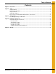
Table of Contents Contents Chapter 1 Introduction ..........................................................................................................................................4 Chapter 2 Safety .....................................................................................................................................................5 Safety Guidelines ..................................................................................................................................
1. Introduction READ THIS MANUAL carefully to learn how to properly use and install equipment. Failure to do so could result in personal injury or equipment damage. INSPECT the shipment immediately upon arrival. The customer is responsible for ensuring that all quantities are correct. The customer should report and note any damage or shortage on the bill of lading to justify their claim to the transport company.
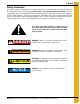
2. Safety Safety Guidelines This manual contains information that is important for you, the owner/operator, to know and understand. This information relates to protecting personal safety and preventing equipment problems. It is the responsibility of the owner/operator to inform anyone operating or working in the area of this equipment of these safety guidelines. To help you recognize this information, we use the symbols that are defined below. Please read the manual and pay attention to these sections.
2. Safety General Safety Statement Our foremost concern is your safety and the safety of others associated with grain handling equipment. This manual is to help you understand safe operating procedures and some problems that may be encountered by the operator and other personnel. As owner and/or operator, you are responsible to know what requirements, hazards, and precautions exist and inform all personnel associated with the equipment or in the area. Safety precautions may be required from the personnel.
2. Safety Safety Instructions Our foremost concern is your safety and the safety of others associated with this equipment. We want to keep you as a customer. This manual is to help you understand safe operating procedures and some problems that may be encountered by the operator and other personnel. As owner and/or operator, it is your responsibility to know what requirements, hazards, and precautions exist and to inform all personnel associated with the equipment or in the area.
2. Safety Prepare for Emergencies Be prepared if fire starts. Keep a first aid kit and fire extinguisher handy. Keep emergency numbers for doctors, ambulance service, hospital, and fire department near your telephone. Keep Emergency Equipment Quickly Accessible Wear Protective Clothing Wear close-fitting clothing and safety equipment appropriate to the job. Eye Protection Remove all jewelry. Tie long hair up and back. Gloves Wear safety glasses at all times to protect eyes from debris.
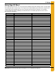
2. Safety Safety Sign-Off Sheet As a requirement of O.S.H.A., it is necessary for the employer to train the employee in the safe operating and safety procedures for this auger. This sign-off sheet is provided for your convenience and personal record keeping. All unqualified persons are to stay out of the work area at all times. It is strongly recommended that another qualified person who knows the shut down procedure be in the area in the event of an emergency.
2. Safety Proper Storage of Grain Bin/Silo Materials Prior to Construction Wet storage stain (rust) will develop when closely packed bundles of galvanized material, such as sidewall and roof sheets, have moisture present. Inspect roof and sidewall bundles on arrival for any moisture. If moisture is present, it must not be allowed to remain between the sheets. Separate the sheets or panels immediately and wipe them down. Spray with a light oil or diesel fuel.
3. Safety Decals Roof Damage Warning and Disclaimer The manufacturer does not warrant any roof damage caused by excessive vacuum or internal pressure from fans or other air moving systems. Adequate ventilation and/or “makeup air” devices should be provided for all powered air handling systems. The manufacturer does not recommend the use of downward flow systems (suction). Severe roof damage can result from any blockage of air passages.
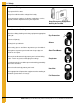
3. Safety Decals ATTENTION: The decal shown below should be present on the outside of the door cover of the 2 ring, 24" porthole door cover and the roof manway cover. If a decal has been damaged or is missing in any of these locations, contact the manufacturer for a free replacement decal. GSI Decals 1004 E. Illinois St. Assumption, IL. 62510 Phone: 1-217-226-4421 Rotating flighting will kill or dismember. Flowing material will trap and suffocate. Crusted material will collapse and suffocate.
3. Safety Decals ATTENTION: The decal shown below should be present on the outside of the door cover of the 2 ring, 24" porthole door cover and the roof manway cover. If a decal has been damaged or is missing in any of these locations, contact the manufacturer for a free replacement decal. GSI Decals 1004 E. Illinois St. Assumption, IL. 62510 Phone: 1-217-226-4421 WARNING DON’T DO UNLOADING INSTRUCTIONS: 1. Use CENTER FLOOR OUTLET ONLY until NO grain remains above this outlet. 2.
4. Installation Instructions Special 90' 2 Ring Door Instructions IMPORTANT: This GSI commercial 2 ring door is designed for use in the 2.66" corrugation 90' diameter NCL tank. This door should not be installed in any tank not manufactured by GSI. Door Placement The commercial 2 ring door is installed in the bottom 2 rings. The door should normally be placed in line with the conveyor. The center of the door must be positioned directly below the vertical seam of the ring above it.
4. Installation Instructions Jamb Plate Assembly The jamb plates are bolted between the inner and outer door frame weldments (NCWT0266 (outer) and NCWT0265 (inner)). The left jamb plate (NCWT0276L) has a “L” cut out in the plate. See Figure 4B for “L” detailed orientation. The jamb plates bolt to the frame weldments using 7/16" x 2-1/2" bin bolts (S-9444) and special recessed nuts (S-8479). Bolt heads should be orientated to outside of bin.
4. Installation Instructions Inner Door Assembly The inner door hinges (NCWT0254) are bolted to the inner door frame weldment through tapped holes. (See detail B in Figure 4C.) Attach using 3/8" x 5/8" bolts (S-7185) and washer (S-248). The 2 ring door requires eight (8) total latch bar holders (WD-6234) assembled to the inner door frame weldment. Washers will be used to adjust the distance between the frame and the latch bar holder for the best fit of the inner doors.
4. Installation Instructions Inner Door Assembly (Continued) Figure 4D shows the hinge and handle assembly onto the upper and lower inner doors. Note the hinge orientation in detail C of Figure 4D. 5/16" x 3/4" Bolts (S-275) and nuts (S-396) are used at most attachment points. See Figure 4D for 5/16" x 1-1/4" bolt (S-277) and 5/16" x 3/4" truss head bolt (S-4303) usage.
4. Installation Instructions Inner Door Assembly (Continued) The upper and lower door assemblies can now be assembled to the inner door weldment. Attach the door assemblies to the hinges using 3/8" x 4-1/2" bolts (S-1443), nuts (S-456) and washers (S-248). Adjust bearing pins and latch bar holders for best fit and tighten all bolts. (See Figure 4E.
4. Installation Instructions Outer Door Assembly Attach three (3) reinforcement channels (NCWT0162), two (2) hinges (NCWT0170) and two (2) retaining brackets (WD-033) to the outer door cover with decals (NCWT0161D). Decals should be orientated to inside of bin. Apply foam seal strip (S-8610) all along outer cover to seal tank. See Figure 4F for bolt usage.
4. Installation Instructions Outer Door Assembly (Continued) Attach outer cover angle (NCWT0168) to the outer door weldment using 5/16" x 1-1/4" bolts (S-277), nuts (S-396) and washers (S-845) for all connections. Attach hinge weldment (NCWT0165) and latch plate (NCWT0166) to outer cover angle (NCWT0168). See detail D in Figure 4G for orientation. The outer cover then attaches to the hinges with 3/8" x 4-1/2" bolt (S-1443), nuts (S-456) and washers (S-248). Assembled outer cover (See Figure 4F on Page 19.
4. Installation Instructions Sidewall and Stiffener Door Attachment Attach seal weldment (NCWT0258) to the inner and outer door weldments using eight (8) 3/8" x 1" standard bolt (S-7469), special sealing washer (S-10102) and nut (S-456). (See Figure 4H.
4. Installation Instructions Sidewall and Stiffener Door Attachment (Continued) Attach sidewall to outside of jamb plates. Use 3/8" x 1-1/2" (S-5060) bin bolt and standard nuts (S-456) to attach sidewall to jamb plates. Place corrugated sealing strip (CWT-0053) between outer and inner edges of the sidewall to jamb plate connection. Caulk around the sealing strip and around the sidewall to header connection as well. (See Figure 4I.
4. Installation Instructions Sidewall and Stiffener Door Attachment (Continued) Position 2 ring door stiffener weld (NCWT0218) under base stiffener sitting on top of 2 ring door header. Attach header, base stiffer and 2 ring door stiffener together with 3/4" x 5" full threaded bolt (S-7324), anchor bolt washer (HT-635), washer (S-866) and nut (S-234). (See detail F in Figure 4J.) After all final adjustments to the door have been made, the anchor bolts should be drilled in place through the external frame.
NOTES 24 PNEG-1884 Special 90' Externally Stiffened 2 Ring Door for Use with Enhanced Stiffeners
5. Warranty GSI Group, LLC Limited Warranty The GSI Group, LLC (“GSI”) warrants products which it manufactures to be free of defects in materials and workmanship under normal usage and conditions for a period of 12 months after sale to the original end-user or if a foreign sale, 14 months from arrival at port of discharge, whichever is earlier.
This equipment shall be installed in accordance with the current installation codes and applicable regulations, which should be carefully followed in all cases. Authorities having jurisdiction should be consulted before installations are made. GSI Group 1004 E. Illinois St. Assumption, IL 62510-0020 Phone: 1-217-226-4421 Fax: 1-217-226-4420 www.gsiag.