2.
All information, illustrations, photos and specifications in this manual are based on the latest information available at the time of publication. The right is reserved to make changes at any time without notice. 2 PNEG-1859 2.
Table of Contents Contents Chapter 1 Introduction .......................................................................................................................................... 4 Chapter 2 Safety ..................................................................................................................................................... 5 Safety Guidelines ..................................................................................................................................
1. Introduction READ THIS MANUAL carefully to learn how to properly use and install equipment. Failure to do so could result in personal injury or equipment damage. INSPECT the shipment immediately upon arrival. The customer is responsible for ensuring that all quantities are correct. The customer should report and note any damage or shortage on the bill of lading to justify their claim to the transport company.
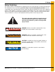
2. Safety Safety Guidelines This manual contains information that is important for you, the owner/operator, to know and understand. This information relates to protecting personal safety and preventing equipment problems. It is the responsibility of the owner/operator to inform anyone operating or working in the area of this equipment of these safety guidelines. To help you recognize this information, we use the symbols that are defined below. Please read the manual and pay attention to these sections.
2. Safety General Safety Statement Our foremost concern is your safety and the safety of others associated with grain handling equipment. This manual is to help you understand safe operating procedures and some problems that may be encountered by the operator and other personnel. As owner and/or operator, you are responsible to know what requirements, hazards, and precautions exist and inform all personnel associated with the equipment or in the area. Safety precautions may be required from the personnel.
2. Safety Safety Instructions Our foremost concern is your safety and the safety of others associated with this equipment. We want to keep you as a customer. This manual is to help you understand safe operating procedures and some problems that may be encountered by the operator and other personnel. As owner and/or operator, it is your responsibility to know what requirements, hazards, and precautions exist and to inform all personnel associated with the equipment or in the area.
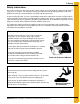
2. Safety Prepare for Emergencies Be prepared if fire starts. Keep a first aid kit and fire extinguisher handy. Keep emergency numbers for doctors, ambulance service, hospital, and fire department near your telephone. Keep Emergency Equipment Quickly Accessible Wear Protective Clothing Wear close-fitting clothing and safety equipment appropriate to the job. Eye Protection Remove all jewelry. Gloves Tie long hair up and back. Wear safety glasses at all times to protect eyes from debris.
2. Safety Safety Sign-Off Sheet As a requirement of O.S.H.A., it is necessary for the employer to train the employee in the safe operating and safety procedures for this auger. This sign-off sheet is provided for your convenience and personal record keeping. All unqualified persons are to stay out of the work area at all times. It is strongly recommended that another qualified person who knows the shut down procedure be in the area in the event of an emergency. Date Employee Name PNEG-1859 2.
2. Safety Proper Storage of Grain Bin/Silo Materials Prior to Construction Wet storage stain (rust) will develop when closely packed bundles of galvanized material, such as sidewall and roof sheets, have moisture present. Inspect roof and sidewall bundles on arrival for any moisture. If moisture is present, it must not be allowed to remain between the sheets. Separate the sheets or panels immediately and wipe them down. Spray with a light oil or diesel fuel.
2. Safety General Information Read this manual carefully. This manual will provide instructions on building the sidewall and stiffeners. You will also need to consult other instructions in building the tank. These include, but may not be limited to: A stiffener and sidewall gauge layout chart. If such a chart is not included with this manual, contact GSI. Roof instructions must be followed. Roof instructions are included in this manual.
2. Safety Construction Procedures and Lifting Jack Usage NOTE: The roof and top ring or 2 rings will be installed prior to the beginning of bin lifting/jacking procedures. Refer all other procedures on sidewall and stiffener installation prior to the start of construction. 1. Consider the starting location of the bin, relative to the location of doors and other accessories. Proper placement of lifting jacks in relationship to anchor bolts could make a difference in final locations.
3. Safety Decals Roof Damage Warning and Disclaimer The manufacturer does not warrant any roof damage caused by excessive vacuum or internal pressure from fans or other air moving systems. Adequate ventilation and/or “makeup air” devices should be provided for all powered air handling systems. The manufacturer does not recommend the use of downward flow systems (suction). Severe roof damage can result from any blockage of air passages.
3. Safety Decals ATTENTION: The decal shown below should be present on the outside of the door cover of the 2 ring, 24" porthole door cover and the roof manway cover. If a decal has been damaged or is missing in any of these locations, contact the manufacturer for a free replacement decal. GSI Decals 1004 E. Illinois St. Assumption, IL. 62510 Phone: 1-217-226-4421 Rotating flighting will kill or dismember. Flowing material will trap and suffocate. Crusted material will collapse and suffocate.
3. Safety Decals ATTENTION: The decal shown below should be present on the outside of the door cover of the 2 ring, 24" porthole door cover and the roof manway cover. If a decal has been damaged or is missing in any of these locations, contact the manufacturer for a free replacement decal. GSI Decals 1004 E. Illinois St. Assumption, IL. 62510 Phone: 1-217-226-4421 WARNING DON’T DO UNLOADING INSTRUCTIONS: 1. Use CENTER FLOOR OUTLET ONLY until NO grain remains above this outlet. 2.
4. Decal Sheet Placement NOTE: On 3 post bins the top ring is not normally stiffened except for 42' diameter and larger bins with stiffeners, (one per sidewall panel). Refer stiffener to sidewall attachment detail and specific gauge sheet for the bin. Figure 4A 3 Post (Three (3) rows of stiffeners used on each sidewall sheet.) 16 PNEG-1859 2.
5.
5. Bolting Requirements Stiffener to Sidewall Connections 3 Post Tanks Figure 5B NOTE: Some locations in the lower regions of the tank utilize close punched sheets where the stiffener will attach more frequently. 18 PNEG-1859 2.
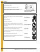
5. Bolting Requirements Bolting and Hardware Requirements Identifying Bolt Grades Under no condition shall any other bolts be substituted for those supplied by GSI. CAUTION Grade 2 Bolts Grade 2 bolts are designated with a plain head and are not used in GSI grain bins/silos. Grade 5 Bolts Grade 5 bolts are designated by three (3) slash marks on the head. All 5/16" diameter bolts are to be grade 5 or higher.
5. Bolting Requirements Refer to 2.66" commercial tank bolting requirements for complete bolt usage. 0.3125" x 0.750" Pre-assembled with a steel backed neoprene washer. This bolt is used to connect horizontal and vertical seams for 14 gauge and thinner sidewall sheets to each other. It is also used in attaching roof panels to the top sidewall sheet and attaching roof panels and flashing to the center collar. 0.3125" x 1.250" Pre-assembled with a steel backed neoprene washer.
5. Bolting Requirements Refer to 2.66" commercial tank bolting requirements for complete bolt usage. (Continued) NOTE: 3/8" x 1-1/2" (S-5060) or 3/8" x 2" (S-9445) Bolts are provided for laminated stiffeners and splices. 0.375" x 1.000" Pre-assembled with a steel backed neoprene washer. This bolt is used in horizontal and vertical seams for 13 gauge through 13 gauge laminate sidewall to attach the sheets to each other.
5. Bolting Requirements Refer to 2.66" commercial tank bolting requirements for complete bolt usage. (Continued) 0.375" x 2.000" Pre-assembled steel backed neoprene washer. This bolt is used in overlapping seams on 8 gauge to 9 gauge laminated sidewall sheets and to connect 6 gauge laminated rings to one another. It is also used to attach stiffener to sidewall on 6 gauge laminated sidewall sheets. 0.4375" x 2.500" Pre-assembled steel backed neoprene washer.
5. Bolting Requirements Refer to 2.66" commercial tank bolting requirements for complete bolt usage. (Continued) 0.4375" x 2.000" Pre-assembled steel backed neoprene washer. This bolt is used in the horizontal seams of 6 gauge figurate pattern laminated sidewall. The standard 7/16" nut, S-7332, will be used in conjunction with this bolt. 0.375" x 1.000" Hex flanged head without a plastic sealing washer. This bolt is used to splice the stiffeners together on the flanges.
5. Bolting Requirements Refer to 2.66" commercial tank bolting requirements for complete bolt usage. (Continued) This 7/16" nut is to be installed at all locations where the 7/16" x 2-1/2" bin bolt S-9444 is installed (9QL, 8QL and 6FL). NOTE: Outside stiffened bins with sidewall that is 10 gauge laminated or thicker will have three (3) sealing washers per sheet provided loose. See the instructions for installation of these loose sealing washers.
5.
6. Caulking Details Caulking Detail for Standard (Non-Laminated) Sheets Figure 6A Standard and Quad Punched Sidewall Sheets as Viewed from Outside Apply one strip of caulking near the outside edge of the outer sheet and between the outer two (2) rows of bolts, refer to Figure 6A. A strip of caulking 10" long, should be placed along the horizontal seams. Before bolting the next ring into place, apply one strip of caulking 10" long on the front of the underlapped sheet at each joint.
6. Caulking Details Caulking Detail for Laminated Quad Pattern Sheets Figure 6C PNEG-1859 2.
6. Caulking Details Caulking Detail for Laminated Figurate Pattern Sheets Figure 6D 28 PNEG-1859 2.
6. Caulking Details When bolting the two (2) assembled/laminated sheets to each other, apply one strip of caulking near the outside edge of the outer sheet, between the outer two (2) rows of bolts and outside the last row of bolts. (See Figure 6E.) A strip of caulking 12" long should be placed along the horizontal seams. Before bolting the next ring into place, apply one strip of caulking 12" long on the front of the under lapped sheet at each joint.
7. Installation Base Angle Installation On the lower edge of the final bottom ring, attach the base angle ring. Before lowering the bin, sealing provision need to be taken for the entire underneath side of the base angle. (See Figure 7A.) Next, lower the bin onto the foundation and check for an adequate seal. Sealing the base of the bin after final construction is done by various methods and materials, based on materials available, preferences of the customer, etc.
7. Installation Anchor Bolt Detail NOTE: Contact GSI engineering for 135' anchor bolt detail. 2.66" Sidewall Gauges NOTE: Some color codes are different than those used for stiffeners.
8. 2.66" Commercial Tank Stiffener Instructions (Outside Stiffened) 2.
8. 2.66" Commercial Tank Stiffener Instructions (Outside Stiffened) Commercial Stiffeners for 2.66'' Corrugation Figure 8A PNEG-1859 2.
8. 2.66" Commercial Tank Stiffener Instructions (Outside Stiffened) Commercial Stiffeners for 2.66'' Corrugation (Continued) Figure 8B 34 PNEG-1859 2.
8. 2.66" Commercial Tank Stiffener Instructions (Outside Stiffened) 2.66'' Corrugation Commercial Stiffeners Splice Details When installing bottom stiffeners, you may find that in some cases the stiffener with base plate attached will not rest on the foundation (due to unlevel foundation, etc.). Shim plates have been furnished and should be used to fill opening between base plate and concrete.
8. 2.66" Commercial Tank Stiffener Instructions (Outside Stiffened) Figure 8D See Page 32 for usage chart. Figure 8E 36 PNEG-1859 2.
8. 2.66" Commercial Tank Stiffener Instructions (Outside Stiffened) See Page 32 for usage chart. Figure 8F PNEG-1859 2.
8. 2.66" Commercial Tank Stiffener Instructions (Outside Stiffened) Figure 8G 38 PNEG-1859 2.
8. 2.66" Commercial Tank Stiffener Instructions (Outside Stiffened) Figure 8H PNEG-1859 2.
8. 2.66" Commercial Tank Stiffener Instructions (Outside Stiffened) Figure 8I 40 PNEG-1859 2.
8. 2.66" Commercial Tank Stiffener Instructions (Outside Stiffened) Figure 8J PNEG-1859 2.
8. 2.66" Commercial Tank Stiffener Instructions (Outside Stiffened) Non-Laminated Stiffener to Sidewall Detail Figure 8K Outside Stiffened Non-Laminated Stiffener to Sidewall Detail 42 PNEG-1859 2.
8. 2.66" Commercial Tank Stiffener Instructions (Outside Stiffened) Laminated Stiffener to Sidewall Detail Figure 8L Outside Stiffened Laminated Stiffener to Sidewall Detail (11 Gauge laminated only.) PNEG-1859 2.
8. 2.66" Commercial Tank Stiffener Instructions (Outside Stiffened) Laminated Stiffener to Sidewall Detail (Continued) Figure 8M Outside Stiffened Laminated Stiffener to Sidewall Detail (10 Gauge laminated and thicker only.) 44 PNEG-1859 2.
8. 2.66" Commercial Tank Stiffener Instructions (Outside Stiffened) Special Detail for 10 Gauge and Thicker Laminated Sidewall See bolting requirements on Page 17. Figure 8N Outside Stiffened Laminated Stiffener to Sidewall Detail (10 Gauge laminated sidewall or thicker only.) PNEG-1859 2.
8. 2.66" Commercial Tank Stiffener Instructions (Outside Stiffened) 3 Stiffeners per Sidewall Sheet Commercial Stiffener Starting Location - 2.66'' Reverse Corrugation Outside Stiffener Only For sidewall stiffener connections use 3/8" x 1" bin bolt except horizontal seam. Stiffeners will bolt every 8". NOTE: Splice plate and laminated stiffener to sidewall connection generally use 3/8" x 1-1/2" bin bolts. Consult the bolting and hardware requirements section on Page 19 for complete details.
8. 2.66" Commercial Tank Stiffener Instructions (Outside Stiffened) Wind Ring Assembly Figure 8P 1. To connect wind ring pipe to the stiffeners, attach with 3/8" x 1" bolts through the flange of the stiffener. In some cases field drilling of wind ring locations may be required. 2. Attach wind ring pipe section to stiffener using two (2) 3/8" x 6" (S-7248) wind ring clamps. 3. Place pipes end-to-end without overlapping.
9. 2.66" Commercial Tank Roof Instructions Roof Beam Stiffener Sidewall Attachment Attach the roof beam stiffener (CRP-7150) to the sidewall using 3/8" x 1-1/2" bin bolt (S-5060) and nut (S-456). Next, field drill four (4) extra holes in the sidewall to match the beam stiffener. Place a corrugation spacer (S-7041) and a steel backed neoprene washer between the beam stiffener and sidewall at each hole location (8X total). (See Figure 9A.
9. 2.66" Commercial Tank Roof Instructions Tension Coupler and Tension Plate Connection Attach tension plate coupler (CRP-7146) to roof beam stiffener (CRP-7150) and bracket (CRP-7151) using four (4) 1/2" x 1-1/2" bolts (S-3728) and nut (S-3729). Attach tension plate (CRP-7149) to tension plate coupler (CRP-7146) using nine (9) 3/4" x 2-3/4" bolts (S-8387), washers (S-866) and nuts (S-234). Bolt must be inserted from the outside wall of the tank as shown.
9. 2.66" Commercial Tank Roof Instructions Center Collar Placement With two (2) sidewall rings in place, position the center collar at a height of 39' - 11-7/8" to the bottom of the center collar as shown in Figure 9C. Figure 9C Roof Beam Splice Splice upper (CRP-7144), middle (CRP-7076) and lower (CRP-7160) roof beams together using 3/4" x 3" bolts (S-8127) and nut (S-234). Note the orientation of the splice plate.
9. 2.66" Commercial Tank Roof Instructions Roof Beam to Tension Coupler and Center Collar Attach the roof beam to the tension coupler and center collar using 1/2" x 2" bolts (S-8268) and nuts (S-3729). It is best to set the beams in assembled pairs with all purlins loosely attached. Pairs of beams should be set by approximately quartering the roof and then evenly filling in between the quarters. The first sets of beams that should be set are the pairs with X-bracing.
9. 2.66" Commercial Tank Roof Instructions Purlin Attachment to Roof Beams (Refer to Figure 9H on Page 54 and Figure 9I on Page 55 detail B1-K1.) Location B1 Attach two (2) purlin clips (CRP-6373) to each side of the beam at purlin location B1 using three (3) 1/2" x 1-1/2" bolt (S-3728) and nut (S-3729). Attach purlin (CRP-6370) to purlin clip (CRP-6373) using four (4) 3/8" x 1-1/2" bolt (S-7928) and flange nut (S-9373).
9. 2.66" Commercial Tank Roof Instructions Purlin Attachment to Roof Beams (Continued) Location F1 Attach four (4) purlin clips, two (2) (CRP-6383) at the lower side of holes and two (2) (CRP-6393) at the upper set of holes at purlin location F1 using six (6) 5/8" x 2" bolts (S-4329) and nuts (S-4110). Attach purlin (CRP-7152) to purlin clip (CRP-6383) and (CRP-6393) using six (6) 3/4" x 2" bolts (S-869) and nuts (S-234).
9. 2.66" Commercial Tank Roof Instructions Purlin Attachment to Roof Beams (Continued) Figure 9H 54 PNEG-1859 2.
9. 2.66" Commercial Tank Roof Instructions Purlin Attachment to Roof Beams (Continued) Figure 9I PNEG-1859 2.
9. 2.66" Commercial Tank Roof Instructions X-Bracing Layout NOTE: See Figure 9H on Page 54 and Figure 9I on Page 55 for hardware callouts. Figure 9J 56 PNEG-1859 2.
9. 2.66" Commercial Tank Roof Instructions X-Bracing Layout (Continued) Figure 9K A total of eight (8) X-bracing bays are used for the 135' roof. They should be spaced out as evenly as possible. Four (4) X-bracing bays should be put up first, quartering the roof. Then place the next four (4) X-bracing bays between the original four (4) bays. Finally, fill in between all X-bracing bays with standard pairs keeping an even weight distribution on the center collar. (See Figure 9K.
9. 2.66" Commercial Tank Roof Instructions Z-Collar Assembly Figure 9L 58 PNEG-1859 2.
9. 2.66" Commercial Tank Roof Instructions Z-Collar Assembly (Continued) (Refer to Figure 9L on Page 58.) Attach all Z-collars to roof beams using 1/2" x 1-1/2" bolts (S-3728), nuts (S-3729) and washer (S-2121) on the top only. Leave the bolt loose on the D1 Z-collar (CRP-6344). This bolt will also be used when placing the roof panel.
9. 2.66" Commercial Tank Roof Instructions Lower Flange Brace Instructions Refer to Figure 9M and Figure 9N. NOTE: The purlins and Z-collars are hidden for clarity reasons. The lower flange brace consists of two (2) brace clips (CRP-6450) attached to the bottom of every roof beam. The brace clips (CRP-6450) are attached using 1/2" x 1-1/2" bolts (S-3728) and 1/2" nut (S-3729). (See detail - lower flange ring in Figure 9H on Page 54 for attachment detail.
9. 2.66" Commercial Tank Roof Instructions Lower Roof Panel Attachment Figure 9O PNEG-1859 2.
9. 2.66" Commercial Tank Roof Instructions Lower Roof Panel Attachment (Continued) (Refer to Figure 9O on Page 61.) The intermediate roof panel (CRP-6342) and lower roof panel (CRP-6343) will overlap at the G1 purlin (CRP-6454). Apply two (2) beads of tube caulking at this overlap. The lower roof panel (CRP-6343) attaches to the eave in four (4) places. Use 5/16" x 1-1/4" bin bolt (S-277) and flange nut (S-3611) to connect large eave clip (CRP-5325) and intermediate eave clip (CRP-5327) to the sidewall.
9. 2.66" Commercial Tank Roof Instructions Upper Roof Panel Attachment Figure 9P PNEG-1859 2.
9. 2.66" Commercial Tank Roof Instructions Upper Roof Panel Attachment (Continued) (Refer to Figure 9P on Page 63.) The upper roof panel (CRP-6341) attaches to the intermediate Z-collar (CRP-6344) using 5/16" x 1-1/4" bolts (S-277) and flange nuts (S-3611). At the rib of the upper panel, a top roof clip (CRP-4829) should be bolted between the panel and Z-collar. The upper part of the panel attaches to the A1 Z-collar (CRP-6367) using 5/16" x 1-1/4" bolts (S-277) and flange nuts (S-3611).
10. 2.66" Commercial Tank Accessories Installation Roof Vent Assembly The following instructions are for assembling and installing the wire grill guard roof vent. Before beginning assembly, check the packing list to ensure all components have been received. The unit is easiest assembled in the upside down position as shown in Figure 10C on Page 66. Locate the roof vent as shown in Figure 10G on Page 67. Figure 10A Roof Panel Figure 10B Center Collar Caulking Detail PNEG-1859 2.
10. 2.66" Commercial Tank Accessories Installation Assembly 1. Turn one roof vent housing (MIS-6778) upside down. (See Figure 10C.) 2. Insert 5/16" x 1-1/4" bin bolt with neoprene washer through the hole in the side of the roof vent. Place jamb nut onto the bolt and tighten. (See Figure 10C.) 3. Slide one eyelet of grill guard onto the 5/16" bin bolt. 4. Insert 5/16" x 1-1/4" bin bolt with neoprene washer through the other side of the roof vent, through jamb nut and other eyelet of grill guard.
10. 2.66" Commercial Tank Accessories Installation Installation 7. If the roof sheet does not have a pre-punched hole for the roof vent, a hole must be cut. Cut the hole to match the roof vent. The inside edge of the hole should be approximately 15" from the eave. (See Figure 10G.) 8. Place the three (3) foam strips on roof sheet, as shown in Figure 10F. Position roof vent over foam strips and bolt down using 5/16" x 3/4" bin bolts and nuts. NOTE: See Figure 10G for lower two (2) bolts of vent.
10. 2.66" Commercial Tank Accessories Installation Roof Exhauster Placement The figure shown is the recommended roof exhauster placement on the 135' bin. A Z-shape reinforcement piece (CRP-6447) is sent with 135' roofs with exhausters. The reinforcement piece should be placed roughly 28.00" from the middle of the upper roof beam splice. That dimension is taken from the upper face of the Z-reinforcement piece.
10. 2.66" Commercial Tank Accessories Installation Roof Exhauster Placement (Continued) Figure 10I PNEG-1859 2.
10. 2.66" Commercial Tank Accessories Installation Safety Ring Placement The safety ring is set up for the bottom hole of the top panel. A total of seventeen (17) pieces of tubing are shipped for the 135' roof. At the splice between two (2) pieces, insert the 1" - 6 x 6" fully threaded screw into one piece and run the two (2) nuts halfway onto the all thread screw. Then insert the next piece of pipe onto the screw.
10. 2.66" Commercial Tank Accessories Installation Temperature Cable Layout Figure 10K shows the GSI recommendation for the 135' commercial bin temperature cable layout, based on a temperature cable manufacturer’s system. This detail is provided solely for the purpose of facilitating proper support bracket placement. It is fully the responsibility of the dealer, customer, contractor or said agent of such parties to confirm details of the system to be used.
10. 2.
10. 2.66" Commercial Tank Accessories Installation Temperature Cable Bracket (CRP-6205) Assembly Instructions (Optional) Figure 10L shows the assembly of the CRP-6205 temperature cable bracket. Note, only one bracket should be used per roof beam. NOTES: 1. Do not attach weights to temperature cables, secure bottom of cables with a light twine to the floor. 2. No roof beam shall support more than one cable. 3. If single center cable exists, consult GSI. Figure 10L PNEG-1859 2.
10. 2.66" Commercial Tank Accessories Installation Inside Ladder Installation The following are special instructions for assembling inside ladders in 135' diameter commercial bins. Ladder Standoff Detail Figure 10M Ladder Standoff Detail (for standard bins) 74 PNEG-1859 2.
10. 2.66" Commercial Tank Accessories Installation Ladder Section Assembly Two (2) LDR-4317 splice plates are required to attach each ladder section. The head of the bolt should be to the inside of the ladder with the splice plate on the outside as shown. Use 5/16" x 3/4" bolts for all connections. (See Figure 10N.) NOTE: With most installations, the last ladder section installed to reach either the ground or the intermediate platform will need to be cut to fit. Figure 10N PNEG-1859 2.
10. 2.66" Commercial Tank Accessories Installation Inside Ladder Placement The inside ladder package includes the ladder, starter brackets, standoff brackets, reinforcement straps and ending bracket. Begin by positioning the ladder directly under the manway roof panel and install the starter bracket as shown in Figure 10O. Place the standoff brackets every horizontal seam or 32" vertically on the sidewall sheets. A strap is then used from one standoff bracket to the next.
10. 2.66" Commercial Tank Accessories Installation Inside Ladder Placement (Continued) Figure 10P Outside Stiffened NOTE: Be sure to push ladder sections up and tighten. Do not tighten ladder section splices with ladder sections hanging under their own weight. Now all standoff brackets and straps must be installed every 32" and attached to each 4' section required. Figure 10Q Un-assembled Reinforcing Strap Figure 10R Assembled Reinforcing Strap PNEG-1859 2.
10. 2.66" Commercial Tank Accessories Installation Inside Ladder Bottom Bracket The bottom ladder section may need to be cut off if the length is too long. Cut the bottom section at least 12" from the bottom of the floor. Attach the bottom inside ladder brackets (LDR-5133) to the last ladder section using the six (6) holes per ladder rail. You may need to drill out the holes in the last ladder section with a 3/8" drill bit.
10. 2.66" Commercial Tank Accessories Installation 135' 2 Ring Door Instructions IMPORTANT: This GSI commercial 2 ring door is designed for use in the 2.66" corrugation 135' diameter NCL tank. This door should not be installed in any tank not manufactured by GSI. Door Placement The commercial 2 ring door is installed in the bottom 2 rings. The door should normally be placed in line with the conveyor. The center of the door must be positioned directly below the vertical seam of the ring above it.
10. 2.66" Commercial Tank Accessories Installation Jamb Plate Assembly The jamb plates are bolted between the inner and outer door frame weldments (NCWT0246 (outer) and NCWT0247 (inner)). The left jamb plate (NCWT0265L) has a “L” cut out in the plate. See Figure 10U for “L” detailed orientation. The jamb plates bolt to the frame weldments using 7/16" x 2-1/2" bin bolts (S-9444) and special recessed nuts (S-8479). Bolt heads should be orientated to outside of bin. Figure 10U 80 PNEG-1859 2.
10. 2.66" Commercial Tank Accessories Installation Inner Door Assembly The inner door hinges (NCWT0254) are bolted to the inner door frame weldment through tapped holes. (See detail B in Figure 10V.) Attach using 3/8" x 5/8" bolts (S-7185) and washer (S-248). The 2 ring door requires eight (8) total latch bar holders (WD-6234) assembled to the inner door frame weldment. Washers will be used to adjust the distance between the frame and the latch bar holder for the best fit of the inner doors.
10. 2.66" Commercial Tank Accessories Installation Inner Door Assembly (Continued) Figure 10W shows the hinge and handle assembly onto the upper and lower inner doors. Note the hinge orientation in detail C of Figure 10W. 5/16" x 3/4" Bolts (S-275) and nuts (S-396) are used at most attachment points. See Figure 10W for 5/16" x 1-1/4" bolt (S-277) and 5/16" x 3/4" truss head bolt (S-4303) usage.
10. 2.66" Commercial Tank Accessories Installation Inner Door Assembly (Continued) The upper and lower door assemblies can now be assembled to the inner door weldment. Attach the door assemblies to the hinges using 3/8" x 4-1/2" bolts (S-1443), nuts (S-456) and washers (S-248). Adjust bearing pins and latch bar holders for best fit and tighten all bolts. (See Figure 10X.) Figure 10X PNEG-1859 2.
10. 2.66" Commercial Tank Accessories Installation Outer Door Assembly Attach three (3) reinforcement channels (NCWT0162), two (2) hinges (NCWT0170) and two (2) retaining brackets (WD-033) to the outer door cover with decals (NCWT0161D). Decals should be orientated to inside of bin. Apply foam seal strip (S-8610) all along outer cover to seal tank. See Figure 10Y for bolt usage. Figure 10Y 84 PNEG-1859 2.
10. 2.66" Commercial Tank Accessories Installation Outer Door Assembly (Continued) Attach outer cover angle (NCWT0168) to the outer door weldment using 5/16" x 1-1/4" bolts (S-277), nuts (S-396) and washers (S-845) for all connections. Attach hinge weldment (NCWT0165) and latch plate (NCWT0166) to outer cover angle (NCWT0168). See detail D in Figure 10Z for orientation. The outer cover then attaches to the hinges with 3/8" x 4-1/2" bolt (S-1443), nuts (S-456) and washers (S-248).
10. 2.66" Commercial Tank Accessories Installation Sidewall and Stiffener Door Attachment Attach seal weldment (NCWT0258) to the inner and outer door weldments using eight (8) 3/8" x 1" standard bolt (S-7469), special sealing washer (S-10102) and nut (S-456). (See Figure 10AA.) Figure 10AA 86 PNEG-1859 2.
10. 2.66" Commercial Tank Accessories Installation Sidewall and Stiffener Door Attachment (Continued) Attach sidewall to outside of jamb plates. Use 7/16" x 2-1/2" (S-9444) bin bolt and recessed nuts (S-8479) to attach sidewall to jamb plates. Place corrugated sealing strip (CWT-0053) between outer and inner edges of the sidewall to jamb plate connection. Caulk around the sealing strip and around the sidewall to header connection as well. (See Figure 10AB.
10. 2.66" Commercial Tank Accessories Installation Sidewall and Stiffener Door Attachment (Continued) Position 2 ring door stiffener weld (NCWT0218) under base stiffener sitting on top of 2 ring door header. Attach header, base stiffer and 2 ring door stiffener together with 3/4" x 5" full threaded bolt (S-7324), anchor bolt washer (HT-635), washer (S-866) and nut (S-234). (See detail F in Figure 10AC.
11. Warranty GSI Group, LLC Limited Warranty The GSI Group, LLC (“GSI”) warrants products which it manufactures to be free of defects in materials and workmanship under normal usage and conditions for a period of 12 months after sale to the original end-user or if a foreign sale, 14 months from arrival at port of discharge, whichever is earlier.
This equipment shall be installed in accordance with the current installation codes and applicable regulations, which should be carefully followed in all cases. Authorities having jurisdiction should be consulted before installations are made. GSI Group 1004 E. Illinois St. Assumption, IL 62510-0020 Phone: 1-217-226-4421 Fax: 1-217-226-4420 www.gsiag.