Bin Manager Temperature Cable Support Bracket Instructions Instruction Manual PNEG-1810 Date: 04-11-12 PNEG-1810
PNEG-1810 Bin Manager Temperature Cable Support Bracket Instructions
Table of Contents Contents Chapter 1 Introduction ..........................................................................................................................................4 Chapter 2 Safety .....................................................................................................................................................5 Safety Guidelines ..................................................................................................................................
1. Introduction READ THIS MANUAL carefully to learn how to properly use and install equipment. Failure to do so could result in personal injury or equipment damage. INSPECT the shipment immediately upon arrival. The customer is responsible for ensuring that all quantities are correct. The customer should report and note any damage or shortage on the bill of lading to justify their claim to the transport company.
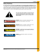
2. Safety Safety Guidelines This manual contains information that is important for you, the owner/operator, to know and understand. This information relates to protecting personal safety and preventing equipment problems. It is the responsibility of the owner/operator to inform anyone operating or working in the area of this equipment of these safety guidelines. To help you recognize this information, we use the symbols that are defined below. Please read the manual and pay attention to these sections.
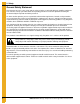
2. Safety General Safety Statement Our foremost concern is your safety and the safety of others associated with grain handling equipment. This manual is to help you understand safe operating procedures and some problems that may be encountered by the operator and other personnel. As owner and/or operator, you are responsible to know what requirements, hazards, and precautions exist, and inform all personnel associated with the equipment or in the area. Safety precautions may be required from the personnel.
2. Safety Safety Instructions Our foremost concern is your safety and the safety of others associated with this equipment. We want to keep you as a customer. This manual is to help you understand safe operating procedures and some problems that may be encountered by the operator and other personnel. As owner and/or operator, it is your responsibility to know what requirements, hazards, and precautions exist, and to inform all personnel associated with the equipment or in the area.
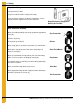
2. Safety Prepare for Emergencies Be prepared if fire starts. Keep a first aid kit and fire extinguisher handy. Keep emergency numbers for doctors, ambulance service, hospital, and fire department near your telephone. Keep Emergency Equipment Quickly Accessible Wear Protective Clothing Wear close-fitting clothing and safety equipment appropriate to the job. Eye Protection Remove all jewelry. Gloves Tie long hair up and back. Wear safety glasses at all times to protect eyes from debris.
3. Decals The manufacturer does not warrant any roof damage caused by excessive vacuum or internal pressure from fans or other air moving systems. Adequate ventilation and/or “makeup air” devices should be provided for all powered air handling systems. The manufacturer does not recommend the use of downward flow systems (suction). Severe roof damage can result from any blockage of air passages. Running fans during high humidity/cold weather conditions can cause air exhaust or intake ports to freeze.
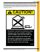
3. Decals ATTENTION: The decal shown below should be present on the outside of the door cover of the 2 ring, 24" porthole door cover and roof manway cover. If a decal has been damaged or is missing in any of these locations, contact the manufacturer for a free replacement decal. GSI Decals 1004 E. Illinois St. Assumption, IL. 62510 Phone: 1-217-226-4421 Rotating flighting will kill or dismember. Flowing material will trap and suffocate. Crusted material will collapse and suffocate.
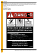
3. Decals ATTENTION: The decal shown below should be present on the outside of the door cover of the 2 ring, 24" porthole door cover and roof manway cover. If a decal has been damaged or is missing in any of these locations, contact the manufacturer for a free replacement decal. GSI Decals 1004 E. Illinois St. Assumption, IL. 62510 Phone: 1-217-226-4421 WARNING DON’T DO UNLOADING INSTRUCTIONS: 1. Use CENTER FLOOR OUTLET ONLY until NO grain remains above this outlet. 2.
4.
4.
4.
4.
4.
5. Temperature cable support packages for eave height of less than or equal to 40' 5" Eave Heights of Less than or Equal to 40' 5" 1. All 18' through 42' packages shall span one roof panel. 2. A rafter support system will be necessary for temperature cable installation in farm tanks 18' through 42' in diameters that have eave height less than 40' 4". 3. All packages include hanging angles and a cable support channel. 4. Each set of rafters should carry only one temperature cable. 5.
5. Temperature cable support packages for eave height of less than or equal to 40' 5" 18'-30' Temperature Cable Support Assembly for Farm Roofs with Eave Heights of 40' 5" or Less External mount instructions continue on Page 49. Internal mount instructions continue on Page 19.
5.
5. Temperature cable support packages for eave height of less than or equal to 40' 5" 33'-42' Temperature Cable Support Assembly for Farm Roofs with Eave Heights of 40' 5" or Less External mount instructions continue on Page 49. Internal mount instructions continue on Page 21.
5.
5.
6. Temperature cable support system for eave height of less than or equal to 40' 5" Eave Heights of Less than or Equal to 40' 5" 1. All 48' packages shall span three (3) roof panels. 2. The package includes bracing Z-channels for the roof rafters. Hanging angle and cable support channels. 3. Each set of rafters carry only one temperature cable. 4. Once the farm roof system has been installed, installation of the cable support packages may proceed as follows. 5.
6. Temperature cable support system for eave height of less than or equal to 40' 5" 48' Temperature Cable Support Assembly for Farm Roofs with Eave Heights of 40' 5" or Less External mount instructions continue on Page 49. Internal mount instructions continue on Page 25.
6.
6. Temperature cable support system for eave height of less than or equal to 40' 5" External mount instructions continue on Page 49. Internal mount instructions continue on Page 27.
6. Temperature cable support system for eave height of less than or equal to 40' 5" 24' Temperature Cable Support Assembly for 2 Post Bins with Farm Roof and No Height Restrictions (Continued) External mount instructions continue on Page 49. Internal mount instructions continue on Page 28.
6.
6. Temperature cable support system for eave height of less than or equal to 40' 5" BMGR-30002EC BMGR-27002EC Temperature Cable Package Part # External mount instructions continue on Page 49. Internal mount instructions continue on Page 30.
6.
6. Temperature cable support system for eave height of less than or equal to 40' 5" BMGR-36002EC External mount instructions continue on Page 49. Internal mount instructions continue on Page 32.
6.
7. Temperature cable support packages for eave height greater than 40' 5" Eave Heights Greater than 40' 5" 1. All 27' through 36' packages shall span one roof panel. 2. A rafter support system will be necessary for temperature cable installation in commercial tanks 27' through 36' in diameters that have an eave height of greater than 40' 4". 3. All packages include hanging angle and cable support channel. 4. Each set of rafters should carry only one temperature cable. 5.
7. Temperature cable support packages for eave height greater than 40' 5" 27' Temperature Cable Support Assembly for 3 Post Bins with Farm Roof and No Height Restrictions External mount instructions continue on Page 49. Internal mount instructions continue on Page 35.
7. Temperature cable support packages for eave height greater than 40' 5" 27' Temperature Cable Support Assembly for 3 Post Bins with Farm Roof and No Height Restrictions (Continued) See Pages 29 and 30 for rafter installation instructions. Rafters span one roof panel.
7. Temperature cable support packages for eave height greater than 40' 5" 30' Temperature Cable Support Assembly for 3 Post Bins with Farm Roof and No Height Restrictions External mount instructions continue on Page 49. Internal mount instructions continue on Page 37.
7. Temperature cable support packages for eave height greater than 40' 5" 30' Temperature Cable Support Assembly for 3 Post Bins with Farm Roof and No Height Restrictions (Continued) See Pages 29 and 30 for rafter installation instructions. Rafters span one roof panel.
7. Temperature cable support packages for eave height greater than 40' 5" BMGR-3300-EC Temperature Cable Package Part # External mount instructions continue on Page 49. Internal mount instructions continue on Page 39.
7.
7. Temperature cable support packages for eave height greater than 40' 5" 36' Temperature Cable Support Assembly for 3 Post Bins with Farm Roof and No Height Restrictions External mount instructions continue on Page 49. Internal mount instructions continue on Page 41.
7. Temperature cable support packages for eave height greater than 40' 5" 36' Temperature Cable Support Assembly for 3 Post Bins with Farm Roof and No Height Restrictions (Continued) See Pages 31 and 32 for 36' roof rafter installation instructions. Roof rafters span one roof panel.
7. Temperature cable support packages for eave height greater than 40' 5" 36' Temperature Cable Support Assembly for 3 Post Bins with Farm Roof and No Height Restrictions (Continued) See Pages 31 and 32 for 36' roof rafter installation instructions. Roof rafters span one roof panel.
8. Temperature cable support packages for commercial roofs Commercial Roofs 1. All packages shall span three (3) roof panels. 2. Each set of rafters should carry only one temperature cable. 3. Once the commercial roof system has been installed, installation of the cable support packages may proceed as follows. 4.
8. Temperature cable support packages for commercial roofs 39'-48' Temperature Cable Support Assembly for Commercial Roofs and No Height Restrictions External mount instructions continue on Page 49. Internal mount instructions continue on Page 45.
8.
8.
8.
8.
8.
NOTES 50 PNEG-1810 Bin Manager Temperature Cable Support Bracket Instructions
9. Warranty GSI Group, LLC Limited Warranty The GSI Group, LLC (“GSI”) warrants products which it manufactures to be free of defects in materials and workmanship under normal usage and conditions for a period of 12 months after sale to the original end-user or if a foreign sale, 14 months from arrival at port of discharge, whichever is earlier.
This equipment shall be installed in accordance with the current installation codes and applicable regulations, which should be carefully followed in all cases. Authorities having jurisdiction should be consulted before installations are made. GSI Group 1004 E. Illinois St. Assumption, IL 62510-0020 Phone: 1-217-226-4421 Fax: 1-217-226-4420 www.gsiag.