Inside Ladder Instructions Installation Manual PNEG-1802 Date: 03-08-11 PNEG-1802
PNEG-1802 Inside Ladder Instructions
Table of Contents Contents Chapter 1 Introduction ..........................................................................................................................................4 Chapter 2 Safety .....................................................................................................................................................5 Safety Guidelines ..................................................................................................................................
1. Introduction READ THIS MANUAL carefully to learn how to properly use and install equipment. Failure to do so could result in personal injury or equipment damage. INSPECT the shipment immediately upon arrival. The customer is responsible for ensuring that all quantities are correct. The customer should report and note any damage or shortage on the bill of lading to justify their claim to the transport company.
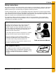
2. Safety Safety Guidelines This manual contains information that is important for you, the owner/operator, to know and understand. This information relates to protecting personal safety and preventing equipment problems. It is the responsibility of the owner/operator to inform anyone operating or working in the area of this equipment of these safety guidelines. To help you recognize this information, we use the symbols that are defined below. Please read the manual and pay attention to these sections.
2. Safety General Safety Statement Our foremost concern is your safety and the safety of others associated with grain handling equipment. This manual is to help you understand safe operating procedures and some problems which may be encountered by the operator and other personnel. As owner and/or operator, you are responsible to know what requirements, hazards and precautions exist and inform all personnel associated with the equipment or in the area. Safety precautions may be required from the personnel.
2. Safety Safety Instructions Our foremost concern is your safety and the safety of others associated with this equipment. We want to keep you as a customer. This manual is to help you understand safe operating procedures and some problems which may be encountered by the operator and other personnel. As owner and/or operator, it is your responsibility to know what requirements, hazards and precautions exist, and to inform all personnel associated with the equipment or in the area.
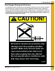
2. Safety Stay Clear of Hoisted Equipment Always use proper lifting/hoisting equipment when assembling or disassembling equipment. Do not walk or stand under hoisted equipment. Always use sturdy and stable supports when needed for installation. Crush Hazard Prepare for Emergencies Be prepared if fire starts. Keep a first aid kit and fire extinguisher handy. Keep emergency numbers for doctors, ambulance service, hospital and fire department near your telephone.
3. Safety Decals Roof Damage Warning and Disclaimer The manufacturer does not warrant any roof damage caused by excessive vacuum or internal pressure from fans or other air moving systems. Adequate ventilation and/or “makeup air” devices should be provided for all powered air handling systems. The manufacturer does not recommend the use of downward flow systems (suction). Severe roof damage can result from any blockage of air passages.
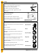
3. Safety Decals ATTENTION: The decal shown below should be present on the outside of the door cover of the 2 ring, 24" porthole door cover and the roof manway cover. If a decal has been damaged or is missing in any of these locations, contact the manufacturer for a free replacement decal. GSI Decals 1004 E. Illinois St. Assumption, IL. 62510 Phone: 1-217-226-4421 Rotating flighting will kill or dismember. Flowing material will trap and suffocate. Crusted material will collapse and suffocate.
3. Safety Decals ATTENTION: The decal shown below should be present on the outside of the door cover of the 2 ring, 24" porthole door cover and the roof manway cover. If a decal has been damaged or is missing in any of these locations, contact the manufacturer for a free replacement decal. GSI Decals 1004 E. Illinois St. Assumption, IL. 62510 Phone: 1-217-226-4421 WARNIN DON’T DO UNLOADING INSTRUCTIONS: 1. Use CENTER FLOOR OUTLET ONLY until NO grain remains above this outlet. 2.
4. Inside Ladder Installation 2.66" Corrugated Farm Bin Inside Ladder Installation (without Stir-Ator) Inside Ladder Placement The inside ladder package includes the ladders, starter brackets and double the amount of standoff brackets. Begin by positioning the ladder directly under the manhole roof panel as shown in Figure 4A and install the starter brackets as shown in Figure 4B on Page 13.
4. Inside Ladder Installation Inside Starter Bracket and Ladder Placement Refer to Figure 4B and follow the correct dimensions as shown. The ladder starter brackets must be located in line with the horizontal seam. Check the 4' ladder section to make sure the ladder rung dimples are to the top surface and attach to the starter brackets using the hole located 1" from top of the ladder. Now all standoff brackets must be installed every 16" and attached to each 4' section required. (See Figure 4C on Page 14.
4. Inside Ladder Installation Inside Ladder Standoff Bracket Requirements Field drilling will be necessary for the standoff brackets located in the middle of the sidewall sheet. Drill two (2) 3/8" diameter holes directly in line with the horizontal seam holes 18-3/4" apart. Continue down the sidewall with standoff brackets at every 16" spacing. Refer to Figure 4C.
4. Inside Ladder Installation Inside Ladder Installation (for Stir-Ator Option) Inside Ladder Placement The inside ladder package for Stir-Ator option includes the ladders and double the amount of short standoff brackets. Begin by positioning the ladder directly under the manhole roof panel as shown in Figure 4D and install the top standoff bracket as shown in Figure 4E on Page 16.
4. Inside Ladder Installation Inside Standoff Bracket and Ladder Placement Refer to Figure 4E and follow the correct dimensions as shown. The top standoff bracket should be in line with the top horizontal seam. Check the 4' ladder section to make sure the ladder rung dimples are to the top surface and attach to the standoff bracket. (See general detail information section on PNEG-1420.) Now all standoff brackets must be installed every 16" and attached to each 4' section required. (See Figure 4F on Page 17.
4. Inside Ladder Installation Inside Ladder Standoff Bracket Requirements Field drilling will be necessary for the standoff brackets located in the middle of the sidewall sheet. Drill two (2) 3/8" diameter holes directly in line with the horizontal seam holes 18-3/4" apart. Continue down the sidewall with standoff brackets at every 16" spacing. Refer to Figure 4F. Figure 4F After completing the inside ladder, it will be necessary to support the bottom of the ladder to the concrete.
4. Inside Ladder Installation 2.66" Corrugated Commercial Grain Bin Inside Ladder Installation (without Stir-Ator) Inside Ladder Placement The inside ladder package includes the ladder, starter brackets and double the amount of standoff brackets. Begin by positioning the ladder directly under the manhole roof panel as shown in Figure 4H and install the starter brackets as shown in Figure 4I on Page 19.
4. Inside Ladder Installation Inside Starter Bracket and Ladder Placement Refer to Figure 4I and Figure 4J and follow the correct dimensions as shown. The ladder starter brackets must be located in line with the horizontal seam. Check the 4' ladder section to make sure the ladder rung dimples are to the top surface and attach to the starter brackets using the hole located 1" from top of the ladder. Now all standoff brackets must be installed every 16" and attached to each 4' section required.
4. Inside Ladder Installation Inside Ladder Standoff Bracket Requirements Field drilling will be necessary for the standoff brackets located in the middle of the sidewall sheet. Drill two (2) holes 3/8" diameter holes directly in line with the horizontal seam holes 18-3/4" apart. Continue down the sidewall with standoff brackets at every 16" spacing. Refer to Figure 4K.
4. Inside Ladder Installation Inside Ladder Installation (for Stir-Ator Option) Inside Ladder Placement The inside ladder package for Stir-Ator option includes the ladders and double the amount of short standoff brackets. Begin by positioning the ladder directly under the manhole roof panel as shown in Figure 4M and install the top standoff bracket as shown in Figure 4N on Page 22.
4. Inside Ladder Installation Inside Standoff Bracket and Ladder Placement Refer to Figure 4N and Figure 4O and follow the correct dimensions as shown. The top standoff bracket should be in line with the top horizontal seam. Check the 4' ladder section to make sure the ladder rung dimples are to the top surface and attach to the standoff bracket. (See general detail information section on PNEG-1420.) Now all standoff brackets must be installed every 16" and attached to each 4' section required.
4. Inside Ladder Installation Inside Ladder Standoff Bracket Requirements Field drilling will be necessary for the standoff brackets located in the middle of the sidewall sheet. Drill two (2) 3/8" diameter holes directly in line with the horizontal seam holes 18-3/4" apart. Continue down the sidewall with standoff brackets at every 16" spacing. Refer to Figure 4P.
4. Inside Ladder Installation 4.00" Corrugated Farm Bin Inside Ladder Installation (without Stir-Ator) Inside Ladder Placement The inside ladder package includes the ladders, starter brackets and double the amount of standoff brackets. Begin by positioning the ladder directly under the manhole roof panel as shown in Figure 4Q and install starter brackets as shown in Figure 4R on Page 25.
4. Inside Ladder Installation Inside Starter Bracket and Ladder Placement Refer to Figure 4R and follow the correct dimensions as shown. The ladder starter brackets must be located in line with the horizontal seam. Check the 4' ladder section to make sure the ladder rung dimples are to the top surface and attach to the starter brackets using the hole located 1" from top of the ladder. Now all standoff brackets must be installed every 22" and attached to each 4' section required.
4. Inside Ladder Installation Inside Ladder Standoffs Requirements Field drilling will be necessary for the standoff brackets located in the middle of the sidewall sheet. Drill two (2) 3/8" diameter holes directly in line with the horizontal seam holes 18-3/4" apart. Continue down the sidewall with standoff brackets at every 22" spacing. Refer to Figure 4S. Figure 4S Inside Ladder Supports After completing the inside ladder, it will be necessary to support the bottom of the ladder to the concrete.
4. Inside Ladder Installation Inside Ladder Installation (for Stir-Ator Option) Inside Ladder Placement The inside ladder package for Stir-Ator option includes the ladders and double the amount of short standoff brackets. Begin by positioning the ladder directly under the manhole roof panel as shown in Figure 4U and install the top standoff bracket as shown in Figure 4V on Page 28.
4. Inside Ladder Installation Inside Standoff Bracket and Ladder Placement Refer to Figure 4V and follow the correct dimensions as shown. The top standoff bracket should be in line with the top horizontal seam. Check the 4' ladder section to make sure the ladder rung dimples are to the top surface and attach to the standoff bracket. (See general detail information section on PNEG-1420.) Now all standoff brackets must be installed every 22" and attached to each 4' section required.
4. Inside Ladder Installation Inside Ladder Standoff Bracket Requirements Field drilling will be necessary for the standoff brackets located in the middle of the sidewall sheet. Drill two (2) 3/8" diameter holes directly in line with the horizontal seam holes 18-3/4" apart. Continue down the sidewall with standoff brackets at every 22" spacing. Refer to Figure 4W.
4. Inside Ladder Installation 4.00" Corrugated Commercial Grain Bin Inside Ladder Installation (without Stir-Ator) Inside Ladder Placement The inside ladder package includes the ladder, starter brackets and double the amount of standoff brackets as the outside ladder package. Begin by positioning the ladder directly under the manhole roof panel as shown in Figure 4X and install the starter brackets as shown in Figure 4Y on Page 31.
4. Inside Ladder Installation Inside Starter Bracket and Ladder Placement Refer to Figure 4Y and follow the correct dimensions as shown. The ladder starter brackets must be located in line with the horizontal seam. Check the 4' ladder section to make sure the ladder rung dimples are to the top surface and attach to the starter brackets using the hole located 1" from top of the ladder. Now all standoff brackets must be installed every 22" and attached to each 4' section required.
4. Inside Ladder Installation Inside Ladder Standoff Bracket Requirements Field drilling will be necessary for the standoff brackets located in the middle of the sidewall sheet. Drill two (2) 3/8" diameter holes directly in line with the horizontal seam holes 18-3/4" apart. Continue down the sidewall with standoff brackets at every 22" spacing. Refer to Figure 4Z. Figure 4Z Inside Ladder Supports After completing the inside ladder, it will be necessary to support the bottom of the ladder to the concrete.
4. Inside Ladder Installation Inside Ladder Installation (for Stir-Ator Option) Inside Ladder Placement The inside ladder package for Stir-Ator option includes the ladders and double the amount of short standoff brackets. Begin by positioning the ladder directly under the manhole roof panel as shown in Figure 4AB and install the top standoff bracket as shown in Figure 4AC on Page 34.
4. Inside Ladder Installation Inside Standoff Bracket and Ladder Placement Refer to Figure 4AC and follow the correct dimensions as shown. The top standoff bracket should be in line with the top horizontal seam. Check the 4' ladder section to make sure the ladder rung dimples are to the top surface and attach to the standoff bracket. (See general detail information section on PNEG-1420.) Now all standoff brackets must be installed every 22" and attached to each 4' section required.
4. Inside Ladder Installation Inside Ladder Standoff Bracket Requirements Field drilling will be necessary for the standoff brackets located in the middle of the sidewall sheet. Drill two (2) 3/8" diameter holes directly in line with the horizontal seam holes 18-3/4" apart. Continue down the sidewall with standoff brackets at every 22" spacing. Refer to Figure 4AD.
4. Inside Ladder Installation 2.66" Corrugated Commercial Hopper Tank 4-9 Rings Inside Ladder Location The inside ladder package includes the ladder, starter brackets and double the amount of standoff brackets. Position the ladder directly under the manhole roof panel as shown in Figure 4AE and install the starter brackets as shown in Figure 4AF on Page 37. Place the standoff brackets every 16" vertically on the sidewall sheets using the horizontal seam holes for every other hole location.
4. Inside Ladder Installation Inside Starter Bracket and Ladder Placement Refer to Figure 4AF and follow the correct dimensions as shown. The ladder starter brackets must be located in line with the horizontal seam. Check the 4' ladder section to make sure the ladder rung dimples are to the top. Attach to the starter brackets using the hole located 1" from top of the ladder.
4. Inside Ladder Installation Inside Ladder Standoff Bracket/Supports Inside Ladder Standoff Bracket Requirements For the standoff brackets, field drill two (2) 3/8" diameter holes 18-3/4" apart directly in line with the horizontal seam holes. Continue down the sidewall with standoff brackets every 16". Refer to Figure 4AG. Figure 4AG Inside Ladder Supports After completing the inside ladder, be sure to support the bottom of the ladder to the concrete.
4. Inside Ladder Installation 2.66" Corrugated Commercial Hopper Tank 10-22 Rings Inside Ladder Placement The inside ladder package includes the ladder, starter brackets and double the amount of standoff brackets. Position the ladder directly under the manhole roof panel as shown in Figure 4AI and install the starter brackets as shown in Figure 4AJ on Page 40. Place the standoff brackets vertically on the sidewall sheets every 16" using the horizontal seam holes for every other hole location.
4. Inside Ladder Installation Inside Starter Bracket and Ladder Placement Refer to Figure 4AJ and follow the correct dimensions as shown. The ladder starter brackets must be located in line with the horizontal seam. Check the 4' ladder section to make sure the ladder rung dimples are to the top. Attach to the starter brackets using the hole located 1" from top of the ladder. It will also be necessary to field drill a 3/8" hole on the ladder section for the starter bracket.
4. Inside Ladder Installation Inside Ladder Standoff Bracket/Supports Inside Ladder Standoff Bracket Requirements For the standoff brackets, field drill two (2) 3/8" diameter holes 18-3/4" apart directly in line with the horizontal seam holes. Continue down the sidewall with standoff brackets every 16". Refer to Figure 4AK. Figure 4AK Inside Ladder Supports After completing the inside ladder, be sure to support the bottom of the ladder to the concrete.
4. Inside Ladder Installation 4.00" Corrugation Farm Commercial Hopper Tank (FCHT) 4-6 Rings Inside Ladder Installation The inside ladder package includes the ladders, starter brackets and double the amount of standoff brackets. Position the ladder directly under the manhole roof panel as shown in Figure 4AM and install starter brackets as shown in Figure 4AN on Page 43. Place the standoff brackets vertically on the sidewall sheets every 22" using the horizontal seam holes for every other hole location.
4. Inside Ladder Installation Inside Starter Bracket and Ladder Placement Refer to Figure 4AN and follow the correct dimensions as shown. The ladder starter brackets must be located in line with the horizontal seam. Check the 4' ladder section to make sure the ladder rung dimples are to the top. Attach to the starter brackets using the hole located 1" from top of the ladder. It will also be necessary to field drill a 3/8" hole on the ladder section for the starter bracket.
4. Inside Ladder Installation Inside Ladder Standoff Bracket/Supports Inside Ladder Standoff Bracket Requirements For the standoff brackets, field drill two (2) 3/8" diameter holes 18-3/4" apart directly in line with the horizontal seam holes. Continue down the sidewall with standoff brackets every 22". Refer to Figure 4AO. Figure 4AO Inside Ladder Supports After completing the inside ladder, be sure to support the bottom of the ladder to the concrete.
4. Inside Ladder Installation 4.00" Corrugation Farm Commercial Hopper Tank (FCHT) 7-9 Rings Inside Ladder Installation The inside ladder package includes the ladders, starter brackets and double the amount of standoff brackets. Position the ladder directly under the manhole roof panel as shown in Figure 4AQ and install starter brackets as shown in Figure 4AR on Page 46. Place the standoff brackets every 22" vertically on the sidewall sheets using the horizontal seam holes for every other hole location.
4. Inside Ladder Installation Inside Starter Bracket and Ladder Placement Refer to Figure 4AR and follow the correct dimensions as shown. The ladder starter brackets must be located in line with the horizontal seam. Check the 4' ladder section to make sure the ladder rung dimples are to the top. Attach to the starter brackets using the hole located 1" from top of the ladder. Now all standoff brackets must be installed every 22" and attached to each 4' section required.
4. Inside Ladder Installation Inside Ladder Standoff Bracket/Supports Inside Ladder Standoff Bracket Requirements For the standoff brackets, field drill two (2) 3/8" diameter holes 18-3/4" apart directly in line with the horizontal seam holes. Continue down the sidewall with standoff brackets every 22". Refer to Figure 4AS. Figure 4AS Inside Ladder Supports After completing the inside ladder, be sure to support the bottom of the ladder to the concrete.
NOTES 48 PNEG-1802 Inside Ladder Instructions
5. Warranty GSI Group, LLC Limited Warranty The GSI Group, LLC (“GSI”) warrants products which it manufactures to be free of defects in materials and workmanship under normal usage and conditions for a period of 12 months after sale to the original end-user or if a foreign sale, 14 months from arrival at port of discharge, whichever is earlier.
This equipment shall be installed in accordance with the current installation codes and applicable regulations which should be carefully followed in all cases. Authorities having jurisdiction should be consulted before installations are made. GSI Group 1004 E. Illinois St. Assumption, IL 62510-0020 Phone: 1-217-226-4421 Fax: 1-217-226-4420 www.gsiag.