
Accessories PNEG-1785 Owner's manual

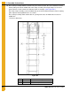

4. Assembly Instructions
46 PNEG-1785 NCHT “X” Series Ladders
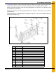
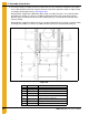
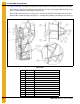
8. Place top of clamp assembly at reference dimension 27-15/16" below the horizontal seam. Attach
access door platform to bin wall using the first hole 9-3/8" to the right of the stiffener. Adjust clamp
assembly to meet platform brace. (See Figure 4AJ.)
Attach platform support bar (LDR-5338) (B) to clamp assembly using 3/8" x 2-1/2" bolt (S-6762)
and flange nut (S-456). Use washer (S-7409) on bolt head and nut side of mounting structure.
DO NOT place nut onto bolt under C-channel (LDR-5342) (C) is mounted to the backside of the
clamp assembly.
Attach platform support bar (LDR-5337) (A) to C-channel (LDR-5342) (C) using 3/8" x 1" bolt (S-7927)
and flange nut (S-456). Use washer (S-7409) on bolt head side of C-channel (LDR-5342) (C).
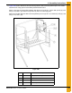
Figure 4AJ
Ref # Part # Description
A LDR-5337 Platform Support Bar
B LDR-5338 Platform Support Bar
C LDR-5342 C-Channel
DClamp Assembly
E 27-15/16" Reference Dimension
F 32" Typical
G Compression Weldment