NCHT “X” Series Ladders Assembly Instructions PNEG-1785 Date: 09-27-13 PNEG-1785
PNEG-1785 NCHT “X” Series Ladders
Table of Contents Contents Chapter 1 Introduction ..........................................................................................................................................4 Chapter 2 Safety .....................................................................................................................................................5 Safety Guidelines ..................................................................................................................................
1. Introduction READ THIS MANUAL carefully to learn how to properly use and install equipment. Failure to do so could result in personal injury or equipment damage. INSPECT the shipment immediately upon arrival. The customer is responsible for ensuring that all quantities are correct. The customer should report and note any damage or shortage on the bill of lading to justify their claim to the transport company.
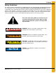
2. Safety Safety Guidelines This manual contains information that is important for you, the owner/operator, to know and understand. This information relates to protecting personal safety and preventing equipment problems. It is the responsibility of the owner/operator to inform anyone operating or working in the area of this equipment of these safety guidelines. To help you recognize this information, we use the symbols that are defined below. Please read the manual and pay attention to these sections.
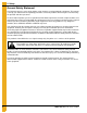
2. Safety General Safety Statement Our foremost concern is your safety and the safety of others associated with this equipment. This manual is to help you understand safe operating procedures and some problems which may be encountered by the operator and other personnel. As owner and/or operator, you are responsible to know what requirements, hazards, and precautions exist and inform all personnel associated with the equipment or in the area. Safety precautions may be required from the personnel.
2. Safety Safety Instructions Our foremost concern is your safety and the safety of others associated with this equipment. We want to keep you as a customer. This manual is to help you understand safe operating procedures and some problems that may be encountered by the operator and other personnel. As owner and/or operator, it is your responsibility to know what requirements, hazards, and precautions exist, and to inform all personnel associated with the equipment or in the area.
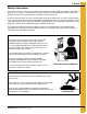
2. Safety Prepare for Emergencies Be prepared if fire starts. Keep a first aid kit and fire extinguisher handy. Keep emergency numbers for doctors, ambulance service, hospital, and fire department near your telephone Keep Emergency Equipment Quickly Accessible Wear Protective Clothing Wear close-fitting clothing and safety equipment appropriate to the job. Eye Protection Remove all jewelry. Tie long hair up and back. Gloves Wear safety glasses at all times to protect eyes from debris.
2. Safety Safety Sign-Off Sheet As a requirement of O.S.H.A., it is necessary for the employer to train the employee in the safe operating and safety procedures for this equipment. This sign-off sheet is provided for your convenience and personal record keeping. All unqualified persons are to stay out of the work area at all times. It is strongly recommended that another qualified person who knows the shut down procedure be in the area in the event of an emergency.
2. Safety Proper Storage Grain Bin/Silo Materials Prior to Construction Wet storage stain (rust) will develop when closely packed bundles of galvanized material, such as sidewall and roof sheets, have moisture present. Inspect roof and sidewall bundles on arrival for any moisture. If moisture is present, it must not be allowed to remain between the sheets. Separate the sheets or panels immediately and wipe them down. Spray with a light oil or diesel fuel.
3. Decals The manufacturer does not warrant any roof damage caused by excessive vacuum or internal pressure from fans or other air moving systems. Adequate ventilation and/or “makeup air” devices should be provided for all powered air handling systems. The manufacturer does not recommend the use of downward flow systems (suction). Severe roof damage can result from any blockage of air passages. Running fans during high humidity/cold weather conditions can cause air exhaust or intake ports to freeze.
3. Decals ATTENTION: The decal shown below should be present on the outside of the door cover of the 2 ring, 24" porthole door cover and the roof manway cover. If a decal has been damaged or is missing in any of these locations, contact the manufacturer for a free replacement decal. GSI Decals 1004 E. Illinois St. Assumption, IL. 62510 Phone: 1-217-226-4421 DANGER Rotating flighting will kill or dismember. Flowing material will trap and suffocate. Crusted material will collapse and suffocate.
3. Decals ATTENTION: The decal shown below should be present on the outside of the door cover of the 2 ring, 24" porthole door cover and the roof manway cover. If a decal has been damaged or is missing in any of these locations, contact the manufacturer for a free replacement decal. GSI Decals 1004 E. Illinois St. Assumption, IL. 62510 Phone: 1-217-226-4421 WARNING UNLOADING INSTRUCTIONS: 1. Use CENTER FLOOR OUTLET ONLY until NO grain remains above this outlet. 2.
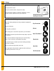
4. Assembly Instructions Left Hand Ladder Assembly 1. Assemble platform brackets (STX-0082 and STX-0009) (C and A) to stiffeners. The outer two (2) brackets (STX-0082 and STX-0009) (C and A) should sit inside of the stiffeners. The middle bracket (LDR-5362) (B) should attach directly to the sidewall using 3/8" x 1-1/2" bin bolt (S-5060) (D) and flange nut (S-9373) (E). Holes will need to be drilled in the sidewall sheet for this bracket.
4. Assembly Instructions 2. Assemble substructure parts to platform brackets. (See Figure 4B.) NOTE: Part # listed below for both 15'-21' and 24'-36' eave platforms.
4. Assembly Instructions 3. Assemble platform pans to substructure components using 5/16" x 3/4" truss head bolt (S-4303) (D) and flange nut (S-3611) (E). (See Figure 4C.) NOTE: Components for both 15'-21' and 24'-36' eave platforms are shown in Figure 4C.
4. Assembly Instructions 4. Attach middle platform bracket (LDR-5362) (A) to platform pans using 5/16" x 3/4" bin bolt (S-275) (B) and flange nut (S-3611) (C). The same 5/16" hardware is used at every location where the two (2) pans on the bottom side of the platform. (See Figure 4D.) Figure 4D Ref # Part # Description A LDR-5362 Platform Bracket B S-275 5/16" x 3/4" Bin Bolt C S-3611 5/16" Flange Nut NOTE: Use same hardware at locations where the platform bracket does not bolt to the pans.
4. Assembly Instructions 5. Assemble all handrail posts to the platform assembly using 5/16" x 3/4" bin bolt (S-275) (F) and flange nut (S-3611) (G). (See Figure 4E.
4. Assembly Instructions 6. Attach all post supports to platform handrail posts and inner portion of platform end short angle using 5/16" x 3/4" bin bolt (S-275) and flange nut (S-3611). (See Figure 4F.) NOTE: Supports mount to the inner portion of the platform substructure.
4. Assembly Instructions 7. Figure 4G shows the assembly of the platform handrails. These must be attached using 5/16" hardware. a. Attach large and small intermediate handrails to platform posts using 5/16" x 3/4" bin bolt (S-275) (C) and flange nut (S-3611) (D). b. Attach long and short upper handrails to platform posts using 5/16" x 2" bolt (S-7877) (H) and flange nut (S-3611) (D). c. Attach short intermediate handrail to platform posts using 5/16" x 3/4" bin bolt (S-275) (C) and flange nut (S-3611) (D).
4. Assembly Instructions 8. Figure 4H shows the assembly of the safety gate bracket (LDR-5185) (B) to the platform post and the assembly of the safety gate (LDR-5218) (A) to the safety gate assembly. Use all four (4) holes in each hinge to mount the safety gate.
4. Assembly Instructions 9. Figure 4I shows the attachment of ladder standoff bracket to the platform bracket using 5/16" x 3/4" bin bolt (S-275) (B) and flange nut (S-3611) (C) and the orientation of the two (2) standoff brackets. Adjust length based upon the wall angle placement. Part # Ref # Description 15'-21' 24'-36' A LDR-5357 LDR-5357 Ladder Standoff Bracket B S-275 S-275 5/16" x 3/4" Bin Bolt C S-3611 S-3611 5/16" Flange Nut Figure 4I 10.
4. Assembly Instructions 11. Attach wall angle to the sidewall sheet using the hole 9-3/8" from the stiffener hole pattern with 3/8" hardware. Assemble the wall bracket to the wall angle using 3/8" x 1" bolt (S-7927) (A) and nut (S-9373) (B) and tighten. Adjust connection of wall bracket to standoff bracket if needed. Also adjust length of the standoff bracket if needed. (See Figure 4K.
4. Assembly Instructions 12. Assemble ladder standoff brackets to wall bracket using 5/16" x 3/4" bin bolt (S-275) (C) and flange nut (S-3611) (D). (See Figure 4L.
4. Assembly Instructions 13. Assemble narrow safety cage bracket, cage hoops and cage splice brackets to the ladder flares and platform posts. This must all be assembled at the same time using 5/16" hardware. (See Figure 4M.) a. Assemble safety cage hoop splices to the platform posts using 5/16" x 3/4" bin bolt (S-275) (E) and flange nut (S-3611) (F) to handrails. b. Assemble narrow safety cage brackets to formed ladder flare using 5/16" x 1-1/4" bolt (S-277) (G) and flange nut (S-3611) (F).
4. Assembly Instructions 14. Attach 4' ladder (4FOOTRF) (C) to ladder flares using 5/16" x 3/4" bin bolt (S-275) (A) and flange nut (S-3611) (B). (See Figure 4N.) Figure 4N Ref # Description A S-275 5/16" x 3/4" Bin Bolt B S-3611 Flange Nut C 4FOOTRF 4' Ladder Section D 26 Part # Second hole must be field drilled.
4. Assembly Instructions Right Hand Ladder Assembly 1. Figure 4O shows the assembly of the platform handrails. These must be attached using 5/16" hardware. a. Attach large and small intermediate handrails to platform posts using 5/16" x 3/4" bin bolt (S-275) (H) and flange nut (S-3611) (I). b. Attach long and short upper handrails to platform posts using 5/16" x 2" bolt (S-7877) (J) and flange nut (S-3611) (I). c.
4. Assembly Instructions 2. Figure 4P shows the attachment of ladder standoff bracket to the platform bracket 5/16" x 3/4" bin bolt (S-275) (B) and flange nut (S-3611) (C) and the orientation of the two (2) standoff brackets. Adjust length based upon the wall angle placement. NOTE: Ladder standoff for both left and right hand ladders are sent with platform. Only use LDR-5385 for the right hand ladder orientation.
4. Assembly Instructions 3. Figure 4Q shows the attachment of the platform wall bracket to the standoff brackets using 5/16" x 3/4" bin bolt (S-275) (B) and flange nut (S-3611) (C). NOTE: Wall bracket (LDR-5173) (A) is for right hand ladder use only.
4. Assembly Instructions 4. Attach wall angle to the sidewall sheet using the hole 9-3/8" for the platform with 3/8" hardware. Assemble the wall bracket to the wall angle using 3/8" x 1" bolt (S-7927) (A) and nut (S-9373) (B) and tighten. Adjust connection of wall bracket to standoff bracket if needed. Also adjust length of standoff bracket if needed. (See Figure 4R.
4. Assembly Instructions 5. Assemble ladder standoff brackets to wall bracket using 5/16" x 3/4" bin bolt (S-275) (C) and flange nut (S-3611) (D). (See Figure 4S.
4. Assembly Instructions 6. Assemble narrow safety cage bracket, cage hoops and cage splice brackets to the ladder flares and platform posts. This must all be assembled at the same time using 5/16" hardware. (See Figure 4T.) a. Assemble safety cage hoop splices to the platform posts using 5/16" x 3/4" bin bolt (S-275) (E) and flange nut (S-3611) (F) to handrails. b. Assemble narrow safety cage brackets to formed ladder flare using 5/16" x 1-1/4" bolt (S-277) (G) and flange nut (S-3611) (F).
4. Assembly Instructions 7. Attach 4' ladder (4FOOTRF) (C) to ladder flares using 5/16" x 3/4" bin bolt (S-275) (A) and flange nut (S-3611) (B). (See Figure 4U.) Figure 4U Ref # Part # Description A S-275 5/16" x 3/4" Bin Bolt B S-3611 5/16" Flange Nut C 4FOOTRF 4' Ladder Section D PNEG-1785 NCHT “X” Series Ladders Second hole must be field drilled.
4. Assembly Instructions 8. Figure 4V shows attachment of platform brace to the platform bracket and to the sidewall sheet. Attach platform brace to platform bracket using 5/16" x 3/4" bin bolt (S-275) (B) and flange nut (S-3611) (C). Attach second wall brace to the first using 5/16" x 3/4" bin bolt (S-275) (B) and flange nut (S-3611) (C). Attach second wall brace to sidewall sheet using 5/16" x 3/4" bin bolt (S-275) (B) and flange nut (S-3611) (C).
4. Assembly Instructions Ladder Safety Cage Sections 1. Attach safety cage bar (LDR-5199) (C) to safety cage hoop (B) using 5/16" x 3/4" bin bolt (S-275) (D) and flange nut (S-3611) (E). 2. Attach LDR-5163 to LDR-5164 using 5/16" x 3/4" bin bolt (S-275) (D) and flange nut (S-3611) (E). (See Figure 4W and Figure 4X.
4. Assembly Instructions Ladder Safety Bell Cage Sections 1. Attach safety cage bar to safety cage hoop using 5/16" x 3/4" bin bolt (S-275) (F) and flange nut (S-3611) (G). 2. Attach safety cage hoop bracket to safety cage hoop using 5/16" x 3/4" bin bolt (S-275) (F) and flange nut (S-3611) (G). (See Figure 4Y, Figure 4Z and Figure 4AA.
4. Assembly Instructions 1. The last ladder section at each intermediate platform and at the bottom may need to be cut off for proper fit. (See Figure 4AB.) 2. Anchor the last ladder section to the intermediate platform with the ladder base using 5/16" x 3/4" bin bolt (S-275) (C) and flange nut (S-3611) (D). You must drill the platform floor to attach the ladder base to the platform. (See Figure 4AB.
4.
4. Assembly Instructions 1. Assemble LDR-5340 to LDR-5341 and LDR-5343 using 1/2" x 2" bolt (S-7811) (G), 1/2" flat washer (S-2120) (F), lock washer (S-236) (E) and nut (S-3729) (D). Finger tighten nut so that each LDR-5341 can slide onto the column. Number of shims (LDR-5343) (C) depends on the column size. Use enough shims make LDR-5341 as flat as possible. See Table for approximation for number of shims. (See Figure 4AC.
4. Assembly Instructions Access Door Platform 1. Figure 4AD shows the assembly of the platform supports and platform floor using 5/16" x 3/4" truss head bolt (S-4303) (F) and flange nut (S-3611) (G) at all the connection points. (Bin wall, compression weldment, support columns and stiffeners hidden for clarity.
4. Assembly Instructions 2. Figure 4AE shows the assembly of the platform post, handrail post, toe plate, upper and intermediate handrail and platform corner posts. Toe kick and post must be assembled at the same time. Attach intermediate handrails (small and large) to platform posts using 5/16" x 3/4" bin bolt (S-275) (H) and flange nut (S-3611) (I). Attach upper handrails (short and long) to platform post using 5/16" x 2" bolt (S-7877) (J) and flange nut (S-3611) (I).
4. Assembly Instructions 3. Figure 4AF shows assembly of wall angle to wall bracket and assembly of platform brace to corner posts. Attach wall angle (LDR-5168) (A) to wall bracket (LDR-5174) using 3/8" x 1" bolt (S-7927) (B) and flange nut (S-9373) (C). Attach platform brace to corner post using 5/16" x 3/4" bin bolt (S-275) (E) and flange nut (S-3611) (F). Attach 24" safety cage bar to platform posts and platform front angle using 5/16" x 3/4" bin bolt (S-275) (E) and flange nut (S-3611) (F).
4. Assembly Instructions 4. Figure 4AG shows attachment of intermediate platform door bracket to platform post. Also shown attachment of safety gate to intermediate platform door bracket. Attach safety gate to intermediate platform door bracket using 5/16" x 3/4" bin bolt (S-275) (C) and flange nut (S-3611) (D). Attach using all four (4) holes in each hinge plate. Attach intermediate platform door bracket to platform post using 5/16" x 3/4" bin bolt (S-275) (C) and flange nut (S-3611) (D).
4. Assembly Instructions 5. Figure 4AH shows assembly of narrow safety cage bracket, cage hoops, cage splice brackets and ladder flares to platform post. NOTE: Make sure the ladder flares are vertical and parallel to the platform posts by adjusting the splice brackets. The ladder should be square to the platform. 6. Figure 4AH shows attachment of intermediate platform ladder bracket to wall bracket. NOTE: Do not mix up left and right intermediate platform ladder bracket.
4. Assembly Instructions 7. Figure 4AI shows the placement of the access door platform in relation to stiffeners. Wall angle for mounting access door platform should be attached to the sidewall at holes 9-3/8" to the right of the stiffener. Do not attempt to mount the wall angle inside of the stiffener.
4. Assembly Instructions 8. Place top of clamp assembly at reference dimension 27-15/16" below the horizontal seam. Attach access door platform to bin wall using the first hole 9-3/8" to the right of the stiffener. Adjust clamp assembly to meet platform brace. (See Figure 4AJ.) Attach platform support bar (LDR-5338) (B) to clamp assembly using 3/8" x 2-1/2" bolt (S-6762) and flange nut (S-456). Use washer (S-7409) on bolt head and nut side of mounting structure.
4. Assembly Instructions 9. Mount C-channel (LDR-5342) (A) on both ends to clamp assembly using middle bolt hole of clamp assembly. The C-channel (LDR-5342) (A) is mounted to the inside of the columns using the middle hole on the clamp assembly. (See Figure 4AK.
4. Assembly Instructions 10. Place clamp assembly down the column every 32" center to center. Be sure to mount C-channel before putting nut onto the middle bolt of the clamp assembly. Do not put clamps less than 32" apart at the base of the column. 36" Column shown as example. (See Figure 4AL.) Place first clamp assembly (center of middle hole) at 30-15/16" below horizontal seam for starting point. Adjust to attach platform brace as needed.
4. Assembly Instructions 11. Attach each end of the wall angle (LDR-5168) (B) to C-channel (LDR-5342) (A) using 5/16" x 3/4" bin bolt (S-275) (C) and flange nut (S-3611) (D). Use washer on bolt head side of C-channel (LDR-5342) (A). (See Figure 4AM.) NOTE: Do not use same hole as platform brace.
4. Assembly Instructions 12. Figure 4AN shows assembly of wall bracket, wall bracket brace and ladder standoffs to wall angle. Attach two (2) wall brackets (LDR-5169) (B) to first three (3) holes of wall angle (LDR-5168) (C) using 3/8" x 1" bolt (S-7927) (K) and flange nut (S-9373) (L). Attach ladder wall bracket brace using 5/16" x 3/4" bin bolt (S-275) (H) and flange nut (S-3611) (I). Attach ladder standoff to wedge using 5/16" x 1" carriage bolt (S-3550) (J) and flange nut (S-3611) (I).
4.
4. Assembly Instructions Ladder to Platform Mounting Details 1. Use special bracket LDR-5344 (B) on the last C-channel. Brackets must be assembled in the orientation shown in Figure 4AP. Attach LDR-5344 (B) to LDR-5168 (A) using the bottom two (2) holes of LDR-5168. Attach 3/8" x 1" bolt (S-7927) (D) and flange nut (S-9373) (E). Attach wall brace assembly (LDR-5197) to C-channel (LDR-5342) using 5/6" x 3/4" bin bolt (S-275) (F) and flange nut (S-3611) (G).
4. Assembly Instructions 2. Attach ladder section to LDR-5161 using 5/16" x 1" bolt (S-277) (A) and flange nut (S-3611) (B). Field drill second hole in ladder section. Attach ladder section to ladder standoff bracket using 5/16" x 3/4" bin bolt (S-275) (C) and flange nut (S-3611) (B). NOTE: Sidewall, stiffeners, columns and bracing compression weldments hidden for clarity of image. (See Figure 4AQ.
4.
4. Assembly Instructions Substructure Platform 1. Attach the wall angle to the sidewall sheet using 3/8" hardware. Assemble the left and right intermediate platform brackets to the wall angles using 3/8" x 1" bolt (S-7927) (K) and nut (S-9373) (L). (See Figure 4AS.) NOTE: Leave all hardware loose until completely assembled. Assemble the platform to the front and back angles and platform brackets using the 5/16" x 3/4" truss head bolt (S-4303) (O) and flange nut (S-3611) (N).
4. Assembly Instructions 2. Assemble the platform wall brace to the intermediate platform front posts and wall angles using 5/16" x 3/4" bin bolt (S-275) (H) and flange nut (S-3611) (F). (See Figure 4AT.) Attach intermediate (large and small) handrail to handrail post using 5/16" x 3/4" bin bolt (S-275) (H) and flange nut (S-3611) (F). Attach upper handrails to platform post using 5/16" x 2" bolt (S-7877) (E) and flange nut (S-3611) (F).
4. Assembly Instructions 3. Assemble the safety cage bars (knee brace) to the posts and front and back angles using 5/16" hardware. (See Figure 4AU.) NOTE: Make sure the intermediate platform is level before tightening hardware.
4. Assembly Instructions 4. Assemble the ladder and ladder brackets to the intermediate platform bracket using 5/16" x 3/4" bin bolt (S-275) (E) and flange nut (S-3611) (F). NOTE: The top ladder rung must be level with the platform floor. (See Figure 4AV.
4. Assembly Instructions 5. Attach the ladder flare to the ladder using 5/16" x 3/4" bin bolt (S-275) (E) and flange nut (S-3611) (F). You must drill the bottom hole through the ladder and use 5/16" hardware. (See Figure 4AW.) Attach the narrow safety cage bracket, cage hoops and cage splice brackets to the ladder flares and platform posts. This must all be assembled at the same time using 5/16" hardware.
4. Assembly Instructions 6. Figure 4AX shows the placement of the access door platform in relation to stiffeners. Wall angle for mounting the substructure platform should be attached to the sidewall at holes 9-3/8" to the left of the stiffener holes. Do not attempt to mount the wall angle inside of the stiffener.
4. Assembly Instructions 7. Place clamp assembly down the column every 32" center to center. Be sure to mount C-channel before putting nut onto the middle bolt of the clamp assembly. Do not put clamps less than 32" apart at the base of the column. 36" Column shown as example. (See Figure 4AY.) NOTE: * Reference dimension. For starting clamp assembly for substructure ladder mounting. NOTE: Place clamp assembly down column with 32" spacing from center of middle hole to center of middle hole.
4. Assembly Instructions 8. Attach wall angle on both ends to C-channel using 5/16" x 3/4" bin bolt (S-275) (C) and flange nut (S-3611) (D). Use washer on bolt head side of channel. (See Figure 4AZ.
4. Assembly Instructions 9. Figure 4BA shows assembly of wall bracket, wall bracket brace and ladder standoff to wall angle. Attach two (2) wall brackets (LDR-5169) (B) to first three (3) holes of wall angle (LDR-5168) (C) using 3/8" x 1" bolt (S-7927) (K) and flange nut (S-9373) (L). Attach ladder wall bracket brace using 5/16" x 3/4" bin bolt (S-275) (H) and flange nut (S-3611) (I). Attach ladder standoff to wedge using 5/16" x 1" carriage bolt (S-3550) (J) and flange nut (S-3611) (I).
4. Assembly Instructions 10. Use special bracket (LDR-5344) (B) on the last C-channel bracket must be assembled in the orientation shown in Figure 4BB. Figure 4BB 64 Ref # Part # Description A LDR-5169 Standard C-Channel Bracket B LDR-5344 Special C-Channel Bracket. Orientate as shown.
4.
NOTES 66 PNEG-1785 NCHT “X” Series Ladders
5. Warranty GSI Group, LLC Limited Warranty The GSI Group, LLC (“GSI”) warrants products which it manufactures to be free of defects in materials and workmanship under normal usage and conditions for a period of 12 months after sale to the original end-user or if a foreign sale, 14 months from arrival at port of discharge, whichever is earlier.
This equipment shall be installed in accordance with the current installation codes and applicable regulations, which should be carefully followed in all cases. Authorities having jurisdiction should be consulted before installations are made. GSI Group 1004 E. Illinois St. Assumption, IL 62510-0020 Phone: 1-217-226-4421 Fax: 1-217-226-4420 www.gsiag.com GSI is a worldwide brand of AGCO Corporation.