42'-135' “X” Series Ladder, Cage and Platform Assembly Instructions PNEG-1773 Date: 12-16-11 PNEG-1773
PNEG-1773 42'-135' “X” Series Ladder, Cage and Platform
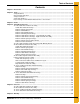
Table of Contents Contents Chapter 1 Introduction ..........................................................................................................................................4 Chapter 2 Safety .....................................................................................................................................................5 Safety Guidelines ..................................................................................................................................
1. Introduction READ THIS MANUAL carefully to learn how to properly use and install equipment. Failure to do so could result in personal injury or equipment damage. INSPECT the shipment immediately upon arrival. The customer is responsible for ensuring that all quantities are correct. The customer should report and note any damage or shortage on the bill of lading to justify their claim to the transport company.
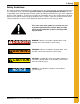
2. Safety Safety Guidelines This manual contains information that is important for you, the owner/operator, to know and understand. This information relates to protecting personal safety and preventing equipment problems. It is the responsibility of the owner/operator to inform anyone operating or working in the area of this equipment of these safety guidelines. To help you recognize this information, we use the symbols that are defined below. Please read the manual and pay attention to these sections.
2. Safety General Safety Statement Our foremost concern is your safety and the safety of others associated with this equipment. This manual is to help you understand safe operating procedures and some problems that may be encountered by the operator and other personnel. As owner and/or operator, you are responsible to know what requirements, hazards, and precautions exist and inform all personnel associated with the equipment or in the area. Safety precautions may be required from the personnel.
2. Safety Safety Instructions Our foremost concern is your safety and the safety of others associated with this equipment. We want to keep you as a customer. This manual is to help you understand safe operating procedures and some problems that may be encountered by the operator and other personnel. As owner and/or operator, it is your responsibility to know what requirements, hazards, and precautions exist, and to inform all personnel associated with the equipment or in the area.
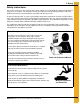
2. Safety Prepare for Emergencies Be prepared if fire starts. Keep a first aid kit and fire extinguisher handy. Keep emergency numbers for doctors, ambulance service, hospital, and fire department near your telephone. Keep Emergency Equipment Quickly Accessible Wear Protective Clothing Wear close-fitting clothing and safety equipment appropriate to the job. Eye Protection Remove all jewelry. Gloves Tie long hair up and back. Wear safety glasses at all times to protect eyes from debris.
2. Safety Safety Sign-Off Sheet As a requirement of O.S.H.A., it is necessary for the employer to train the employee in the safe operating and safety procedures for this equipment. This sign-off sheet is provided for your convenience and personal record keeping. All unqualified persons are to stay out of the work area at all times. It is strongly recommended that another qualified person who knows the shut down procedure be in the area in the event of an emergency.
2. Safety Proper Storage of Grain Bin/Silo Materials Prior to Construction Wet storage stain (rust) will develop when closely packed bundles of galvanized material, such as sidewall and roof sheets, have moisture present. Inspect roof and sidewall bundles on arrival for any moisture. If moisture is present, it must not be allowed to remain between the sheets. Separate the sheets or panels immediately and wipe them down. Spray with a light oil or diesel fuel.
3. Decals The manufacturer does not warrant any roof damage caused by excessive vacuum or internal pressure from fans or other air moving systems. Adequate ventilation and/or “makeup air” devices should be provided for all powered air handling systems. The manufacturer does not recommend the use of downward flow systems (suction). Severe roof damage can result from any blockage of air passages. Running fans during high humidity/cold weather conditions can cause air exhaust or intake ports to freeze.
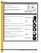
3. Decals ATTENTION: The decal shown below should be present on the outside of the door cover of the 2 ring, 24" porthole door cover and the roof manway cover. If a decal has been damaged or is missing in any of these locations, contact the manufacturer for a free replacement decal. GSI Decals 1004 E. Illinois St. Assumption, IL. 62510 Phone: 1-217-226-4421 Rotating flighting will kill or dismember. Flowing material will trap and suffocate. Crusted material will collapse and suffocate.
3. Decals ATTENTION: The decal shown below should be present on the outside of the door cover of the 2 ring, 24" porthole door cover and the roof manway cover. If a decal has been damaged or is missing in any of these locations, contact the manufacturer for a free replacement decal. GSI Decals 1004 E. Illinois St. Assumption, IL. 62510 Phone: 1-217-226-4421 WARNING DON’T DO UNLOADING INSTRUCTIONS: 1. Use CENTER FLOOR OUTLET ONLY until NO grain remains above this outlet. 2.
NOTES 14 PNEG-1773 42'-135' “X” Series Ladder, Cage and Platform
72'-135' Ladder Eave Platform Assembly Instructions PNEG-1773 42'-135' “X” Series Ladder, Cage and Platform 15
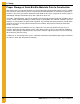
4. Assembly Instructions 72'-135' Ladder Eave Platform Assembly Ladder Eave Platform Package 1. Figure 4A shows the assembly of the platform supports. Use 5/16" hardware at all the connection points. (Platform floor will have to be attached at the same time as support angles.) NOTE: When installing the top wind ring, do NOT use the top set of holes in the stiffener. 2. Figure 4A shows the assembly of the platform floor system. This must all be assembled at the same time using 5/16" hardware.
4. Assembly Instructions Platform and Safety Cage Bar 4. Figure 4B shows the assembly of the platform post and post supports. This must all be assembled at the same time using 5/16" hardware. Figure 4B Platform and Wall Brace 5. Assemble the eave platform wall braces to the platform support and sidewall using 5/16" hardware. (See Figure 4C below and Figure 4D on Page 18.
4.
4. Assembly Instructions Platform and Handrail Package 6. Figure 4E shows the assembly of the platform handrails. These must also be attached using 5/16" hardware.
4. Assembly Instructions Platform and Swing Gate Package 7. Attach the platform gate bracket to the gate before attaching it to the inside platform post using 5/16" hardware. (See Figure 4F below and Figure 4G on Page 21.
4.
4. Assembly Instructions Platform Ladder Bracket Package - Left Hand Side Assembly 8. Attach the wall angle to the sidewall sheet using the hole 9-3/8" from the stiffener hole pattern with 3/8" hardware. Assemble the wall bracket to the wall angle with 3/8" hardware and tighten. (See Figure 4H below and Figure 4I on Page 23.) Attach left and right intermediate platform ladder bracket to the wall bracket and platform support with 5/16" hardware. NOTE: Do not force the wall bracket in or out.
4.
4. Assembly Instructions Platform Ladder Bracket Package - Right Hand Side Assembly 9. Attach the wall angle to the sidewall sheet using the hole 9-3/8" from the stiffener hole pattern with 3/8" hardware. Assemble the wall bracket to the wall angle with 3/8" hardware and tighten. (See Figure 4J below and Figure 4K on Page 25.) Attach left and right intermediate platform ladder bracket to the wall bracket and platform support with 5/16" hardware. NOTE: Do not force the wall bracket in or out.
4.
4. Assembly Instructions Platform and Safety Cage Package 10. Attach the ladder flare to the ladder using 5/16" hardware. You must drill the bottom hole through the ladder and use 5/16" hardware. (See Figure 4L.) 11. Attach the narrow safety cage bracket, cage hoops and cage splice brackets to the ladder flares and platform posts. This must all be assembled at the same time using 5/16" hardware.
4. Assembly Instructions Platform and Safety Cage Splice Bracket 12. Attach the cage splice bracket to the post and cage splice using 5/16" hardware. (See Figure 4M.
4. Assembly Instructions Platform Inside Post Bracket 13. Attach the post bracket to the inside post and bottom stair post using 5/16" hardware. (See Figure 4N.) NOTE: Continue to Page 44 to see remaining ladder and cage layout.
72'-135' Ladder Only Eave Platform Assembly Instructions PNEG-1773 42'-135' “X” Series Ladder, Cage and Platform 29
4. Assembly Instructions Special Order Package Only 72'-135' Ladder Only Eave Platform Package with Manway Guard NOTE: Used when there are no roof stairs. 1. Attach ladder/eave platform handrail bracket (LDR-5304) and ladder/eave platform kick plate splice plate (LDR-5305) to eave handrail post (STX-0076) using 5/16" hardware. LDR-5207 will not be used in this package. (See Figure 4O below and Figure 4P on Page 31.
4.
NOTES 32 PNEG-1773 42'-135' “X” Series Ladder, Cage and Platform
42'-60' Ladder Eave Platform Assembly Instructions PNEG-1773 42'-135' “X” Series Ladder, Cage and Platform 33
4. Assembly Instructions 42'-60' Ladder Eave Platform Assembly Ladder Eave Platform Package 1. Figure 4Q below and Figure 4R on Page 35 shows the assembly of the platform supports. Use 5/16" hardware at all the connection points. (Platform floor will have to be attached at the same time as support angles.) NOTE: When installing the top wind ring, do NOT use the top set of holes in the stiffener. NOTE: Leave all hardware loose until completely assembled. 2.
4. Assembly Instructions Ladder Eave Platform Package (Continued) Figure 4R Platform and Safety Cage Bar 3. Figure 4S shows the assembly of the platform post. This must all be assembled at the same time using 5/16" hardware. NOTE: 24" Safety cage bars are mounted to the inside of the post and the outside of the platform long angle.
4. Assembly Instructions Platform and Handrail Package 4. Figure 4T shows the assembly of the platform handrails. These must also be attached using 5/16" hardware.
4. Assembly Instructions Platform and Swing Gate Package 5. Attach the platform gate bracket to the gate before attaching it to the inside platform post using 5/16" hardware. (See Figure 4U.
4. Assembly Instructions Platform Ladder Bracket Package 6. Attach the wall angle to the sidewall sheet using the hole 9-3/8" from the stiffener hole pattern with 3/8" hardware. Assemble the wall bracket to the wall angle with 3/8" hardware and tighten. (See Figure 4V below and Figure 4W on Page 39.) Attach left and right intermediate platform ladder bracket to the wall bracket and platform support with 5/16" hardware. NOTE: Do not force the wall bracket in or out.
4.
4. Assembly Instructions Platform and Safety Cage Package 7. Attach the ladder flare to the ladder using 5/16" hardware. You must drill the bottom hole through the ladder and use 5/16" hardware. (See Figure 4X.) 8. Attach the narrow safety cage bracket, cage hoops and cage splice brackets to the ladder flares and platform posts. This must all be assembled at the same time using 5/16" hardware. NOTE: Be sure the ladder flares are vertical and parallel to the platform posts by adjusting the splice brackets.
42'-60' Ladder Only Eave Platform Assembly Instructions PNEG-1773 42'-135' “X” Series Ladder, Cage and Platform 41
4.
Ladder and Safety Cage Layout PNEG-1773 42'-135' “X” Series Ladder, Cage and Platform 43
4.
4. Assembly Instructions A 11 Rings A 1st B Ring A 22 Rings B A 1st Ring 11th Ring 2.
D C 22nd C B A 33 Rings B A Ring C 11th Ring B 1st Ring A 37 Rings D 27th Ring C 17th Ring B A 1st Ring 9th Ring 4.
Ladder and Safety Cage Assembly Instructions PNEG-1773 42'-135' “X” Series Ladder, Cage and Platform 47
4. Assembly Instructions NOTE: See table on Page 44 for correct ladder and safety cage layout. 1. Assemble the wall bracket to the wall angle using 3/8" hardware. (See Figure 4AC on Page 49.) NOTE: The wall angle must be assembled on top of the previous wall angle to provide a flat surface to mount the wall bracket. 2. Assemble the wall braces to the wall bracket and the horizontal sidewall seam using 5/16" hardware.
4.
4.
4. Assembly Instructions 4. Assemble the safety cage rail spacer, standard safety cage hoops and cage bars to the ladder using 5/16" hardware. (See Figure 4AE.) 5. Assemble the safety cage rail spacer, bell safety cage hoops and cage bars to the ladder using 5/16" hardware. (See Figure 4AE.) NOTE: See table on Page 44 for correct size of cage bars.
4.
4.
4. Assembly Instructions 6. The last ladder section at each intermediate platform and at the bottom may need to be cut off for proper fit. (See Figure 4AK.) 7. Anchor the last ladder section to the intermediate platform using the ladder base and 5/16" hardware. You must drill the platform floor to attach the ladder base to the platform. (See Figure 4AK.
Ladder Intermediate Platform Package PNEG-1773 42'-135' “X” Series Ladder, Cage and Platform 55
4. Assembly Instructions “X” Series Ladder Intermediate Platform Package Platform Package 1. Attach the wall angle to the sidewall sheet with 3/8" hardware. Assemble the left and right intermediate platform brackets to the wall angles with 3/8" hardware. (See Figure 4AL.) NOTE: Leave all hardware loose until completely assembled. Assemble the platform to the front and back angles and platform brackets using the 5/16" truss bolts. Using 5/16" hardware, assemble the posts.
4. Assembly Instructions Platform Package (Continued) 2. Assemble the platform wall brace to the intermediate platform front posts and wall angles with 5/16" hardware. (See Figure 4AM.) Attach the platform gate bracket to the gate before attaching it to the platform back post using 5/16" hardware. Assemble the top and intermediate handrails to the post using 5/16" hardware.
4. Assembly Instructions Platform and Safety Cage Bar Package 3. Assemble the safety cage bars (knee brace) to the posts and front and back angles using 5/16" hardware. (See Figure 4AN.) NOTE: Be sure the intermediate platform is level before tightening hardware.
4. Assembly Instructions Platform and Ladder Cage Package 4. Assemble the ladder and ladder brackets to the intermediate platform bracket using 5/16" hardware. The top ladder rung must be level with the platform floor. (See Figure 4AO.
4. Assembly Instructions Platform and Cage Package 5. Attach the ladder flare to the ladder using 5/16" hardware. You must drill the bottom hole through the ladder and use 5/16" hardware. (See Figure 4AP below and Figure 4AQ on Page 61.) Attach the narrow safety cage bracket, cage hoops and cage splice brackets to the ladder flares and platform posts. This must all be assembled at the same time using 5/16" hardware.
4. Assembly Instructions Platform and Cage Package (Continued) Figure 4AQ NOTE: See Pages 48-53 for ladder and cage assembly.
NOTES 62 PNEG-1773 42'-135' “X” Series Ladder, Cage and Platform
Sidedraw Ladder Platform Package PNEG-1773 42'-135' “X” Series Ladder, Cage and Platform 63
4. Assembly Instructions “X” Series Sidedraw Ladder Platform Package Platform Package 1. Attach the wall angle to the sidewall sheet with 3/8" hardware. Assemble the left and right intermediate platform brackets to the wall angles with 3/8" hardware. (See Figure 4AR.) NOTE: Leave all hardware loose until completely assembled. Assemble the platform to the front and back angles and platform brackets using the 5/16" truss bolts.
4. Assembly Instructions Platform and Safety Cage Bar Package 2. Assemble platform post and 24" safety cage bar to platform with 5/16" hardware. Attach eave platform wall brace to platform handrail post with 5/16" hardware. (See Figure 4AS.
4. Assembly Instructions Platform and Handrail Package 3. Assemble top and intermediate handrails to the post using 5/16" hardware. (See Figure 4AT.
4. Assembly Instructions Platform and Swing Gate Package 4. Assemble the platform gate bracket to the gate before attaching it to the platform back post using 5/16" hardware. (See Figure 4AU.
4. Assembly Instructions Platform and Safety Cage Package 5. Attach the ladder flare to the ladder using 5/16" hardware. You must drill the bottom hole through the ladder and use 5/16" hardware. (See Figure 4AV.) Attach the narrow safety cage bracket, cage hoops and cage splice brackets to the ladder flares and platform posts. This must all be assembled at the same time using 5/16" hardware. NOTE: Be sure the ladder flares are vertical and parallel to the platform posts by adjusting the splice brackets.
4. Assembly Instructions Platform Ladder Bracket Package 6. Assemble the ladder to ladder brackets using 5/16" hardware. The top ladder rung must be level with the platform floor. (See Figure 4AW below and Figure 4AX on Page 70.) Figure 4AW NOTE: See Pages 48-53 for ladder assembly instructions.
4.
4. Assembly Instructions 7. Platform placed at the bottom of the ring in which sidedraw placed. Figure 4AY shows placement of 7 ring ladder package platform with sidedraw in 7th ring. (See Figure 4AY.) NOTE: Shown for placement purposes only. Ladder mounting parts not shown. See Pages 48-53 for ladder assembly instructions.
Platform Completed Assembly Drawings and Parts List 72 PNEG-1773 42'-135' “X” Series Ladder, Cage and Platform
5. Parts List 1. 72'-135' Ladder Eave Platform Assembly - (See Pages 74-76.) 2. 42'-60' Ladder Eave Platform Assembly - (See Pages 77-79.) 3. “X” Series Ladder Intermediate Platform Package - (See Pages 80-82.) 4. “X” Series Sidedraw Ladder Platform Package - (See Pages 83-85.
5.
5.
5.
5.
5.
5.
5.
5.
5.
5.
5.
5.
NOTES 86 PNEG-1773 42'-135' “X” Series Ladder, Cage and Platform
6. Warranty GSI Group, LLC Limited Warranty The GSI Group, LLC (“GSI”) warrants products which it manufactures to be free of defects in materials and workmanship under normal usage and conditions for a period of 12 months after sale to the original end-user or if a foreign sale, 14 months from arrival at port of discharge, whichever is earlier.
This equipment shall be installed in accordance with the current installation codes and applicable regulations, which should be carefully followed in all cases. Authorities having jurisdiction should be consulted before installations are made. GSI Group 1004 E. Illinois St. Assumption, IL 62510-0020 Phone: 1-217-226-4421 Fax: 1-217-226-4420 www.gsiag.