Fall Restraint Reinforcement Kit Installation Manual PNEG-1753 Date: 03-23-12 PNEG-1753
PNEG-1753 Fall Restraint Reinforcement Kit
Table of Contents Contents Chapter 1 Introduction ..........................................................................................................................................4 Chapter 2 Safety .....................................................................................................................................................5 Safety Guidelines ..................................................................................................................................
1. Introduction READ THIS MANUAL carefully to learn how to properly use and install equipment. Failure to do so could result in personal injury or equipment damage. INSPECT the shipment immediately upon arrival. The customer is responsible for ensuring that all quantities are correct. The customer should report and note any damage or shortage on the bill of lading to justify their claim to the transport company.
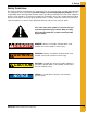
2. Safety Safety Guidelines This manual contains information that is important for you, the owner/operator, to know and understand. This information relates to protecting personal safety and preventing equipment problems. It is the responsibility of the owner/operator to inform anyone operating or working in the area of this equipment of these safety guidelines. To help you recognize this information, we use the symbols that are defined below. Please read the manual and pay attention to these sections.
2. Safety Safety Instructions Our foremost concern is your safety and the safety of others associated with this equipment. We want to keep you as a customer. This manual is to help you understand safe operating procedures and some problems that may be encountered by the operator and other personnel. As owner and/or operator, it is your responsibility to know what requirements, hazards, and precautions exist, and to inform all personnel associated with the equipment or in the area.
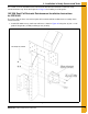
3. Installation in Newly Constructed Tanks This section is for the installation of the Fall Restraint Reinforcement Kit to be installed in newly constructed tanks only. Refer to Chapter 4 on Page 13 for installing in existing tanks. 105'-25K Roof Fall Restraint Reinforcement Installation Instructions for CRP-6945 The center collar and one eave tension plate will need to be drilled to allow for the assembly of this reinforcement kit. 1.
3. Installation in Newly Constructed Tanks 105'-25K Roof Fall Restraint Reinforcement Installation Instructions for CRP-6945 (Continued) 2. Install CRP-6939 inside of the tank and attached to the vertical row of stiffener bolts adjacent to the roof beam stiffener nearest the manway. For a reference, See Figure 3B. Top stiffener bolts are to be removed to install CRP-6939. Replace top stiffener bolts with two (2) 3/8" x 1-1/2" grade 8 bolts with steel back neoprene washers (S-5060).
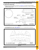
3. Installation in Newly Constructed Tanks 105'-25K Roof Fall Restraint Reinforcement Installation Instructions for CRP-6945 (Continued) 4. Drill holes in the center collar. For a reference, See Figure 3C. The holes must be positioned equidistant between roof rafters and as close as possible to the manway, as shown. Use CRP-6942 to aid in the setup of holes. Figure 3C 5. Install CRP-6942 to the center collar using two (2) 1/2" x 1-1/2" grade 8 bolts (S-3728) and nuts (S-8808).
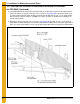
3. Installation in Newly Constructed Tanks 135'-50K Roof Fall Restraint Reinforcement Installation Instructions for CRP-7113 The center collar and one eave tension plate will need to be drilled to allow for the assembly of this reinforcement kit. 1. Install CRP-7007 to every roof beam stiffener as shown in Figure 3E using four (4) 3/8" x 1-1/2" grade 8 flange bolts (S-7928) and flange nuts (S-9373).
3. Installation in Newly Constructed Tanks 135'-50K Roof Fall Restraint Reinforcement Installation Instructions for CRP-7113 (Continued) 2. Install CRP-7003 inside of the tank and attached to the vertical row of stiffener bolts adjacent to the roof beam stiffener nearest the manway. For a reference, See Figure 3F. Top stiffener bolts are to be removed to install CRP-7003. Replace top stiffener bolts with two (2) 3/8" x 1-1/2" grade 8 bolts with steel back neoprene washers (S-5060).
3. Installation in Newly Constructed Tanks 135'-50K Roof Fall Restraint Reinforcement Installation Instructions for CRP-7113 (Continued) 4. Drill holes in the center collar. For a reference, See Figure 3G. The holes must be positioned equidistant between roof rafters and as close as possible to the manway, as shown. Use CRP-7001 to aid in the setup of holes. Figure 3G 5. Install CRP-7001 to the center collar using two (2) 1/2" x 1-1/2" grade 8 bolts (S-3728) and nuts (S-8808).
4. Installation in Existing Tanks This section is for the installation of the Fall Restraint Reinforcement Kit to be retrofit in existing tanks only. See Chapter 3 on Page 7 for installing in newly constructed tanks. 105'-25K Roof Fall Restraint Reinforcement Installation Instructions for CRP-6948 The center collar, all of the roof beam stiffeners and one eave tension plate will need to be drilled to allow for the assembly of this reinforcement kit. 1.
4. Installation in Existing Tanks 105'-25K Roof Fall Restraint Reinforcement Installation Instructions for CRP-6948 (Continued) 2. Install CRP-6943 to every roof beam stiffener as shown in Figure 4B using four (4) 3/8" x 1-1/2" grade 8 flange bolts (S-7928) and flange nuts (S-9373).
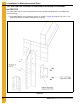
4. Installation in Existing Tanks 105'-25K Roof Fall Restraint Reinforcement Installation Instructions for CRP-6948 (Continued) 3. Install CRP-6939 inside of the tank attached to the vertical row of stiffener bolts adjacent to the roof beam stiffener nearest the manway. For a reference, See Figure 4C. Top stiffener bolts are to be removed to install CRP-6939. Replace the top stiffener bolts with two (2) 3/8" x 1-1/2" grade 8 bolts with steel back neoprene washers (S-5060).
4. Installation in Existing Tanks 105'-25K Roof Fall Restraint Reinforcement Installation Instructions for CRP-6948 (Continued) 5. Drill holes in the center collar. For a reference, See Figure 4D. The holes must be positioned equidistant between roof rafters and as close as possible to the manway, as shown. Use CRP-6942 to aid in the setup of holes. Figure 4D 6. Install CRP-6942 to the center collar using two (2) 1/2" x 1-1/2" grade 8 bolts (S-3728) and nuts (S-8808). For a reference, See Figure 4E.
5. Warranty GSI Group, LLC Limited Warranty The GSI Group, LLC (“GSI”) warrants products which it manufactures to be free of defects in materials and workmanship under normal usage and conditions for a period of 12 months after sale to the original end-user or if a foreign sale, 14 months from arrival at port of discharge, whichever is earlier.
This equipment shall be installed in accordance with the current installation codes and applicable regulations which should be carefully followed in all cases. Authorities having jurisdiction should be consulted before installations are made. GSI Group 1004 E. Illinois St. Assumption, IL 62510-0020 Phone: 1-217-226-4421 Fax: 1-217-226-4420 www.gsiag.