VTDL-48 - 8 x 9 Door Assembly Instruction Manual PNEG-1742 Date: 06-02-10 PNEG-1742
PNEG-1742 VTDL-48 - 8 x 9 Door Assembly
Table of Contents Contents Chapter 1 Safety .....................................................................................................................................................4 Safety Guidelines .................................................................................................................................. 4 General Safety Statement .....................................................................................................................
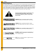
1. Safety Safety Guidelines This manual contains information that is important for you, the owner/operator, to know and understand. This information relates to protecting personal safety and preventing equipment problems. It is the responsibility of the owner/operator to inform anyone operating or working in the area of this equipment of these safety guidelines. To help you recognize this information, we use the symbols that are defined below. Please read the manual and pay attention to these sections.
1. Safety General Safety Statement Our foremost concern is your safety and the safety of others associated with grain handling equipment. This manual is to help you understand safe operating procedures and some problems which may be encountered by the operator and other personnel. As owner and/or operator, you are responsible to know what requirements, hazards and precautions exist and inform all personnel associated with the equipment or in the area. Safety precautions may be required from the personnel.
1. Safety Follow Safety Instructions Carefully read all safety messages in this manual and safety signs on your machine. Keep signs in good condition. Replace missing or damaged safety signs. Be sure new equipment components and repair parts include the current safety signs. Replacement safety signs are available from the manufacturer. Learn how to operate the machine and how to use controls properly. Do not let anyone operate without instruction. Keep your machinery in proper working condition.
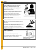
1. Safety Wear Protective Clothing Wear close fitting clothing and safety equipment appropriate to the job. Eye Protection Remove all jewelry. Long hair should be tied up and back. Gloves Safety glasses should be worn at all times to protect eyes from debris. Steel Toe Boots Wear gloves to protect your hands from sharp edges on plastic or steel parts. Wear steel toe boots to help protect your feet from falling debris. Tuck in any loose or dangling shoe strings.
1. Safety Safety Sign-Off Sheet As a requirement of O.S.H.A., it is necessary for the employer to train the employee in the safe operating and safety procedures for this equipment. This sign-off sheet is provided for your convenience and personal record keeping. All unqualified persons are to stay out of the work area at all times. It is strongly recommended that another qualified person who knows the shut down procedure be in the area in the event of an emergency.
2. Safety Decals Roof Damage Warning and Disclaimer The manufacturer does not warrant any roof damage caused by excessive vacuum or internal pressure from fans or other air moving systems. Adequate ventilation and/or “makeup air” devices should be provided for all powered air handling systems. The manufacturer does not recommend the use of downward flow systems (suction). Severe roof damage can result from any blockage of air passages.
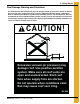
2. Safety Decals ATTENTION: The decal shown below should be present on the outside of the door cover of the 2 ring, 24" porthole door cover and the roof manway cover. If a decal has been damaged or is missing in any of these locations, contact the manufacturer for a free replacement decal. GSI Decals 1004 E. Illinois St. Assumption, IL. 62510 Phone: 1-217-226-4421 Rotating flighting will kill or dismember. Flowing material will trap and suffocate. Crusted material will collapse and suffocate.
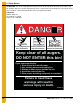
2. Safety Decals ATTENTION: The decal shown below should be present on the outside of the door cover of the 2 ring, 24" porthole door cover and the roof manway cover. If a decal has been damaged or is missing in any of these locations, contact the manufacturer for a free replacement decal. GSI Decals 1004 E. Illinois St. Assumption, IL. 62510 Phone: 1-217-226-4421 WARNIN DON’T DO UNLOADING INSTRUCTIONS: 1. Use CENTER FLOOR OUTLET ONLY until NO grain remains above this outlet. 2.
3. Suggested Tools 1. Forklift or a similar piece of equipment capable of lifting 1500 lbs. at heights above 10'. 2. Welder. 3. Plasma cutter, torch or a similar tool for cutting base plates. 4. Concrete drill for installing 3/4" epoxy type anchors (if anchors are used). 5. 1/2", 7/16" and 1-1/8" drill bits. 6. Sockets and wrenches including 9/16", 5/8", 15/16", 1" and 1-1/4" sizes. 7. Drift pins and/or pry bars.
4. Assembly Instructions Installation of the Large Vehicle Traffic Door in 48' diameter, externally stiffened tanks. Prior to door installation, the tank should be fully erected and anchored. The SCTDL 48-8 x 9 Door is to be installed in the bottom 4 rings of the tank. Adequate provisions should be made for door installation. A list of necessary tools and equipment is attached. Also, some field fabrication and welding will be necessary. 1. The VTDL door is to be installed in the bottom 4 rings of the tank.
4. Assembly Instructions 8. The center column weldment (VTDL-0541) will be installed within the door frame. The bottom of the center column weldment will rest between the column outer cover strip on the threshold weldment. The top of the center column weldment will bolt to the header beam weldment with 3/4" x 2-1/2" bolts. See details B and C on Page 21. Use VTDL-0403 shim plates between the center column and the header beam and threshold weldment.
4. Assembly Instructions 15. To open the door, unbolt the door panels from the door frame. Do not remove the hinges or unbolt the door panels from one another. Swing the door panels open to remove the center column. Provisions should be made to hold the door panels open while the center column is being removed and the bin is being cleaned. Unbolt the top of the center column from the header beam and remove the shim plate.
Continue tank erection as normal until fifth ring from bottom is reached. Note the location of the vertical seams and stiffener columns above the door opening. The fifth ring must be positioned this way for door to fit properly. Assemble door sheets and stiffener columns as shown. It may be necessary to use filler sheets at the door installation location to finish erecting the tank. These sheets must be removed when tank is set and door installation is to begin. Do not caulk filler sheets.
5. Assembly Drawings Door panel assembly (See Page 22.
Remove filler sheets and install threshold weldments. Threshold weldments will either be anchored to the concrete or field welded to a tunnel beam. Do not anchor or field weld threshold weldments until door assembly is completed. Set right and left column weldments on threshold weldments and attach to the sidewall with 3/8" x 1" bin bolts. (Bolts size may vary slightly with sidewall thickness.) The sidewall will be on the outside of the column weldment.
The header beam must slide onto the columns from the inside of the tank. The seal strip atop the header will bolt to the fifth ring from the inside of the tank. Attach the header to the columns with 3/4" x 2-1/2" grade 8 bolts, nuts and washers. Refer to Page 20 for header to column connection details. Required field welding should be done after door is completely installed. Field weld sidewall plates and door attachment plates as shown. Refer to Page 24 for complete weld details.
NOTE: Install header beam onto columns as shown on Page 19. Use 3/4" x 2-1/2" grade 8 bolts with washer on each side. Insert bolt from the column side upward and hand tighten. Be sure that the edge of the threshold plate is aligned with the edge of the column. Field weld threshold plates, sidewall plates and door panel plates after door is completely installed. 5.
NOTE: Center column weld (VTDL-0541) will be installed from the inside of the tank. Place shim plate (VTDL-0403) in position on the threshold weldments. Place bottom of the column near the threshold weldment and tilt the column upward into position. Bolt the column to the header as shown. Install shim plate prior to tightening bolts. Bolts may be hand tightened at this time. Do not fully tighten until door is completely installed. Be sure that all the door panel plates are aligned.
5.
NOTE: Install standard base stiffeners above header beam as shown. Shim stiffeners as necessary and tighten all sidewall and stiffener bolts around the door. Field weld base stiffeners to header beam. It may be necessary too trim the stiffener base plate to match the outer edge of the header beam. Install all hinge pins as shown in detail D. Remove door panel bolts and make sure all door panels swing freely. 5.
All sidewall, stiffener and door assembly bolts must be tight prior to welding of door frame. Shim thresholds and columns as necessary and field weld as shown. Door panels not shown for clarity. 5.
NOTE: Attach angles to columns and header with 3/8" x 1" bin bolts. The outer cover hinge brackets will attach to the outside of the column outer cover flanges. Attach the center post to the header and threshold weldments with 3/8" x 1" bin bolts. Attach reinforcement channels, outer cover handles and latch brackets to the outer cover with 3/8" x 1" bin bolts. Place outer cover assembly in position and insert the hinge pin through the hinge weldment and bracket.
5.
6. Warranty GSI Group, LLC Limited Warranty The GSI Group, LLC (“GSI”) warrants products which it manufactures to be free of defects in materials and workmanship under normal usage and conditions for a period of 12 months after sale to the original end-user or if a foreign sale, 14 months from arrival at port of discharge, whichever is earlier.
This equipment shall be installed in accordance with the current installation codes and applicable regulations which should be carefully followed in all cases. Authorities having jurisdiction should be consulted before installations are made. GSI Group 1004 E. Illinois St. Assumption, IL 62510-0020 Phone: 1-217-226-4421 Fax: 1-217-226-4420 www.gsiag.