
Accessories PNEG-1740 User Manual


12 PNEG-1740 Internally Stiffened Small 2 Ring Door
3. Assembly Instructions
36' 30 Ring or 42'-60' 24 Ring Installation
NOTE: NCWT0206-XXX Must be installed in a 42'-60' diameter tank, 24 rings and smaller.
NCWT0208-XXX Must be installed in a 36' diameter tank, 30 rings and smaller.
1. The commercial 2 ring door may be installed in the bottom 2 rings or in the 2
nd
and 3
rd
rings. If the
bin contains a full floor, the door must be placed in the 2
nd
and 3
rd
rings.
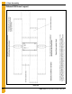
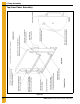
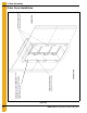
2. The door should normally be placed in line with the conveyor. An intermediate discharge well should
be located near the wall to clear grain from the area of the access door. The door must be positioned
directly above and below the vertical seam as shown in Figure 4A on Page 14.
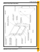
3. The door consists of the following components:
a. Frame weldment
b. Top and bottom inner panel
c. Outer cover assembly
The frame weldment will bolt directly into the sidewall of the tank. The sidewall orientation must be
as shown in Figure 4A on Page 14 and Figure 4B on Page 15.
4. After the door installation is complete, install the base stiffeners on each side of the door frame.
5. Caulk the door frame weldment in the same manner as the sidewall sheets.
6. Install all frame bolts and tighten. Use 3/8" x 1" bin bolts to install door. NOTE: In certain cases,
5/16" x 3/4" bin bolts may be used if sidewall gauges are 14 gauge or thinner.
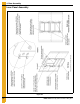
7. Assemble the top and bottom inner panels as shown in Figure 4C on Page 16 and Figure 4D on
Page 17. Please note the orientation of the latches and hinges.
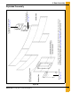
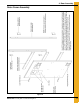
8. Install bearing pins (WD-6224) and latch bar holders (WD-6234) in door frame as shown in detail C
of Figure 4E on Page 18. Use a 5/16" x 2-1/2" bolt to attach the bearing pins to the door frame. The
bolt head should be on the inside of the bin.
9. Attach the latch bar holders to the door frame with a 1/2" x 1-1/2" bolt. Use 1/2" flat washers to adjust
the depth of the latch bar holders. A 1/2" lock washer must also be used on this connection. Do not
fully tighten bearing pins or latch bar holders until the inner door panels have been installed and
adjusted. For a reference, please See Figure 4E on Page 18.
10. Attach assembled top and bottom panels to door frame with 2/8" x 4-1/2" grade 2 bolt and lock nut.
11. Adjust hinges as necessary to allow door panels to open and close smoothly. Also, adjust the bearing
pins so they fit door panel holes. Latch bar holders should be adjusted as necessary until the inner
panel latches operate smoothly.
12. Once the panels have been installed and adjusted, apply a foam seal strip along the door frame to
seal inner panels as shown in Figure 4G on Page 20.
13. Assemble the outer cover as shown in Figure 4F on Page 19. Attach outer cover hinge weldments
to outer cover hinges with 3/8" x 4-1/2" grade 2 bolts and 3/8" lock nuts.
14. Place the following decals: DC-GBC-1A and DC-GBC-1S should be placed on the inner side of
the outer cover; DC-GBC-2A, DC-GBC-2S and DC-1754 must be placed on the outer side of the
outer cover.
15. Attach the outer cover angles (NCWT0205) to the frame weldments with 5/16" x 1-1/4" bin bolts.
Use flat washers over any slotted connections.