Peak Walk Around Assembly Assembly and Installation Manual PNEG-1721 Date: 10-21-09 PNEG-1721
PNEG-1721 Peak Walk Around Assembly
Table of Contents Contents Chapter 1 Safety .................................................................................................................................................. 4 Safety Guidelines ............................................................................................................................... 4 Safety Instructions ..............................................................................................................................
1. Safety Safety Guidelines This manual contains information that is important for you, the owner/operator, to know and understand. This information relates to protecting personal safety and preventing equipment problems. It is the responsibility of the owner/operator to inform anyone operating or working in the area of this equipment of these safety guidelines. To help you recognize this information, we use the symbols that are defined below. Please read the manual and pay attention to these sections.
1. Safety Safety Instructions Our foremost concern is your safety and the safety of others associated with this equipment. We want to keep you as a customer. This manual is to help you understand safe operating procedures and some problems which may be encountered by the operator and other personnel. As owner and/or operator, it is your responsibility to know what requirements, hazards and precautions exist, and to inform all personnel associated with the equipment or in the area.
2.
2.
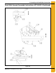
3. Assembly and Installation Instructions See detail A on Page 9. See detail B on Page 9. See Page 9 for assembly details. See detail C on Page 9.
3.
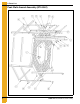
3. Assembly and Installation Instructions Peak Walk Around Assembly Instructions (GT4-5061) (Continued) 1. Begin assembling vertical handrail supports with horizontal handrail supports. 2. Assemble vertical handrail support (GT1-5139) with the other vertical handrail support (GT1-5141) using 5/16" hardware such a way, that both the 3/16" holes align on each component. (See Figure 3C.) Figure 3C 3.
3. Assembly and Installation Instructions 4. Assemble vertical handrail support (GT1-5136), horizontal handrail support (GT1-5137) using 5/16" hardware. (See Figure 3E.) Figure 3E 5. Repeat the assembly Step 4 for three (3) times.
3. Assembly and Installation Instructions 6. Assemble vertical support (GT1-5139) with vertical handrail support (GT1-5142). Assemble this assembly, with horizontal handrail support (GT1-5137) using 5/16" hardware. (See Figure 3G.) Figure 3G 7. Assemble catwalk entry plank (GT1-5135), brackets (GT1-5146, GT1-5147, GT1-5144, GT1-5143), horizontal plank supports (GT1-5133) using 5/16" hardware. (See Figure 3H below and Figure 3I on Page 13.) See detail B on Page 13. See detail A on Page 13.
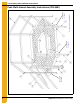
3. Assembly and Installation Instructions Detail A Detail B Figure 3I 8. Assemble catwalk plank (GT1-5134), bracket (GT1-5138), horizontal plank support (GT1-5133) using 5/16" hardware. (See Figure 3J.
3. Assembly and Installation Instructions 9. Repeat assembly Step 8 on Page 13 for four (4) times. Figure 3K 10. Tighten all the hardware. 11. Assemble latch (GT3-0106) as shown using screws (S-2009) and nuts (S-2010). (See Figure 3L.
3. Assembly and Installation Instructions Peak Walk Around Installation Instructions 1. Before installing the Peak Walk Around Assembly on the roof, assemble 7 ea. brackets (GT1-5130) on the roof sheet at the third hole from outside of the roof as shown in Figure 3M. Figure 3M 2. Install the Peak Walk Around Assembly on the roof such a way, the entry would align with the ladder. (See Figure 3N.) Assemble transition supports (GT1-5131 and GT1-5132) using 5/16" hardware as shown in Figure 3N.
3. Assembly and Installation Instructions 3. Fasten horizontal supports to the roof sheet using 1/4" hardware as shown in Figure 3O.
4. Warranty GSI Group, LLC Limited Warranty The GSI Group, LLC (“GSI”) warrants products which it manufactures to be free of defects in materials and workmanship under normal usage and conditions for a period of 12 months after sale to the original end-user or if a foreign sale, 14 months from arrival at port of discharge, whichever is earlier.
This equipment shall be installed in accordance with the current installation codes and applicable regulations which should be carefully followed in all cases. Authorities having jurisdiction should be consulted before installations are made. GSI Group 1004 E. Illinois St. Assumption, IL 62510-0020 Phone: 1-217-226-4421 Fax: 1-217-226-4420 www.gsiag.