
Accessories PNEG-1655 User Manual

5. Assembly Instructions
PNEG-1655 VTDL-135' - 8' x 9' Door Assembly w/ Manway 15
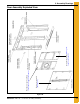
8. The center column weldments (VTDL-0556) will be installed within the door frame. The bottom of the
center column weldment will rest between the column outer cover strip on the threshold weldment.
The top of the center column weldment will bolt to the header beam weldment with 1" x 3-1/2" bolts.
See details B and C on Page 23. Use VTDL-0338 shim plates between center column and header
beam and threshold weldment. Place one shim plate on the threshold weldment splice prior to the
placement of the center column. The center column should be placed inside of the tank with the base
of the column near the threshold weldment splice. Tilt the column upward into position and bolt it to
the header beam. Install the top shim plate. The door panel attachment plates of the column, header
and threshold weldments should be aligned. (See Page 23.) The center column is to be removed
when door is opened; do not field weld to center column. Do not tighten bolts until door panels
are installed.
9. Verify that the door frame is square and all door panel attachment plates are in alignment prior to
installing door panels.
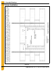
10. Assemble door panels as shown on Page 24. Door panels must be installed in this manner to
maintain proper orientation of hinges. Door hinge plate weldments (VTDL-0574) are to be placed
as shown on Page 24 detail D. Use 7/16" x 2" bolts (S-10114) at door panel splices and hinge plate
weldments. Follow installation details on Page 25 for door panel placement. Use 1" x 3-1/2"
grade 8 bolts to attach door panels to the door fame. Use only enough bolts to hold panels in place
and clamp the panels to the door frame. Be sure that the panels are closed completely and all holes
are aligned. The door panels will be opened later to allow for field welding and sealing. Caulk all along
door panel splices. Use 1" x 3-1/2" grade 8 bolts at these locations. Door attachment plate splices
will be used at all hinge and door attachment plate splice locations. See Page 28 for details.
11. Insert hinge pins (VTDL-0244) through hinge plates on the door panels and column weldments.
See detail E on Page 27. Place 1/2" washer over top of the hinge pin and secure it with 1/8" cotter pin
(S-7241). Tighten all door panel bolts and door frame connection bolts at this time.
12. Attach standard base stiffener weldments above header beam as shown on Page 27. Use 7/16" x 2"
bolts (S-10114) for attaching to seal strip and 7/16" x 2-1/2" bolts for attaching to sidewall plates.
Tighten all sidewall and stiffener bolts at this time. Shim as necessary and field weld stiffeners to
header beam. Base plates may have to be trimmed to align with header beam. (See Page 27.)
13. Anchor threshold weldments to foundation or field weld to tunnel beam. Field weld columns to
threshold weldments. Open door panels and field weld door panel attachment plates of header and
threshold to left and right column weldments. Field weld threshold weldment splice and access cover
plates on column weldments. Welding should be done on both the inside and outside of the door
frame. Refer to Page 29 for complete field welding details.
14. Clean, inspect and paint all welds. Place foam seal strip all along the outer edge of the door panel
assembly to seal door panels. Close door panels and install all door panel bolts with washer on each
side. Be sure that the reinforcement plates are in the proper location. (See Page 30.) Tighten door
panel bolts. Inspect all welds and door assembly bolts at this time. Place decals DC-GBC-1A and
DC-GBC-2A on the inside of the door panels. (See Page 30.) Caulk any gaps around the center
column weldment and threshold weldments.