36'-135' “C” Series Roof Stairs and Handrail Assembly Instructions PNEG-1623 Date: 05-26-09 PNEG-1623
PNEG-1623 Roof Stairs and Handrail Assembly
Table of Contents Contents Chapter 1 Introduction ....................................................................................................................................... 4 Chapter 2 Safety .................................................................................................................................................. 5 Safety Guidelines ...............................................................................................................................
1. Introduction READ THIS MANUAL carefully to learn how to properly use and install equipment. Failure to do so could result in personal injury or equipment damage. INSPECT the shipment immediately upon arrival. The customer is responsible for ensuring that all quantities are correct. The customer should report and note any damage or shortage on the bill of lading to justify their claim to the transport company.
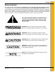
2. Safety Safety Guidelines This manual contains information that is important for you, the owner/operator, to know and understand. This information relates to protecting personal safety and preventing equipment problems. It is the responsibility of the owner/operator to inform anyone operating or working in the area of this equipment of these safety guidelines. To help you recognize this information, we use the symbols that are defined below. Please read the manual and pay attention to these sections.
2. Safety General Safety Statement Our foremost concern is your safety and the safety of others associated with grain handling equipment. This manual is to help you understand safe operating procedures and some problems which may be encountered by the operator and other personnel. As owner and/or operator, you are responsible to know what requirements, hazards and precautions exist and inform all personnel associated with the equipment or in the area. Safety precautions may be required from the personnel.
2. Safety Safety Instructions Our foremost concern is your safety and the safety of others associated with this equipment. We want to keep you as a customer. This manual is to help you understand safe operating procedures and some problems which may be encountered by the operator and other personnel. As owner and/or operator, it is your responsibility to know what requirements, hazards and precautions exist, and to inform all personnel associated with the equipment or in the area.
2. Safety Prepare for Emergencies Be prepared if fire starts. Keep a first aid kit and fire extinguisher handy. Keep emergency numbers for doctors, ambulance service, hospital and fire department near your telephone. Keep Emergency Equipment Quickly Accessible Wear Protective Clothing Wear close fitting clothing and safety equipment appropriate to the job. Eye Protection Remove all jewelry. Gloves Long hair should be tied up and back.
2. Safety Safety Sign-Off Sheet As a requirement of O.S.H.A., it is necessary for the employer to train the employee in the safe operating and safety procedures for this auger. This sign-off sheet is provided for your convenience and personal record keeping. All unqualified persons are to stay out of the work area at all times. It is strongly recommended that another qualified person who knows the shut down procedure be in the area in the event of an emergency.
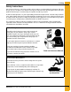
2. Safety Proper Storage Grain Bin/Silo Materials Prior to Construction Wet storage stain (rust) will develop when closely packed bundles of galvanized material, such as sidewall and roof sheets, have moisture present. Inspect roof and sidewall bundles on arrival for any moisture. If moisture is present, it must not be allowed to remain between the sheets. Separate the sheets or panels immediately and wipe them down. Spray with a light oil or diesel fuel.
3. Decals The manufacturer does not warrant any roof damage caused by excessive vacuum or internal pressure from fans or other air moving systems. Adequate ventilation and/or “makeup air” devices should be provided for all powered air handling systems. The manufacturer does not recommend the use of downward flow systems (suction). Severe roof damage can result from any blockage of air passages. Running fans during high humidity/cold weather conditions can cause air exhaust or intake ports to freeze.
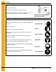
3. Decals ATTENTION: The decal shown below should be present on the outside of the door cover of the 2 ring, 24" porthole door cover and the roof manway cover. If a decal has been damaged or is missing in any of these locations, contact the manufacturer for a free replacement decal. GSI Decals 1004 E. Illinois St. Assumption, IL. 62510 Phone: 1-217-226-4421 Rotating flighting will kill or dismember. Flowing material will trap and suffocate. Crusted material will collapse and suffocate.
3. Decals ATTENTION: The decal shown below should be present on the outside of the door cover of the 2 ring, 24" porthole door cover and the roof manway cover. If a decal has been damaged or is missing in any of these locations, contact the manufacturer for a free replacement decal. GSI Decals 1004 E. Illinois St. Assumption, IL. 62510 Phone: 1-217-226-4421 WARNIN DON’T DO UNLOADING INSTRUCTIONS: 1. Use CENTER FLOOR OUTLET ONLY until NO grain remains above this outlet. 2.
4.
5.
5. Stair Section Three (3) Step Bottom Assembly (LDR-5129) Roof stair to ladder cage attachment angle (LDR-4289) (2). See Figure 7A on Page 23 for placement.
5. Stair Section Four (4) Step Top Assembly (LDR-4239) NOTE: Roof stair leveling shim, (LDR-4258), (not shown) is also included in four (4) step top assembly.
5.
5.
5.
5.
6. Complete Stair Assembly See Figure 7A on Page 23. See Figure 9A on Page 30. Figure 6A NOTE: Start roof stair assembly with three (3) step bottom section (LDR-5129). Center the roof stair sections over the roof panel. Attach the appropriate number of two (2) step, three (3) step or four (4) step sections to the bottom section. Refer Chart on Page 14 for the correct number of sections. 72' and larger bins will require a transition stair package. See details on Pages 31-33 for instructions.
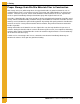
7. Three (3) Step Bottom Three (3) Step Bottom Section (LDR-5129) Figure 7A Begin roof stairs directly above sidewall ladder and adjacent to the manway panel. Roof stair sections are to be centered on roof panel. Begin with three (3) step bottom section (LDR-5129). Align edge of rib spanning angle (LDR-4149) with edge of roof rib. Field drill hole through rib spanning bracket and roof rib. Attach roof stair section to roof rib with 5/16" x 1-1/4" bolts.
8. Manway Handrail 36'-60' w/ Round Manway (Refer to Page 25 and Page 26 for details.) 1. Loosely assemble handrail posts (LDR-4392) to post attach weld (LDR-4228) using 5/16" hardware. 2. Loosely attach corner insert weldment (LDR-4390) to handrail posts. 3. Place pipe handrails (LDR-4398) between the corner insert weldments. After the correct spacing is found, secure with 1/4" self-drilling screws. (See Detail D on Page 26.) 4.
PNEG-1623 Roof Stairs and Handrail Assembly SEE DETAIL B ON PAGE 26 SEE DETAIL A ON PAGE 26 SEE DETAIL C ON PAGE 26 SEE DETAIL D ON PAGE 26 SEE DETAIL E ON PAGE 26 SEE DETAIL F ON PAGE 26 8.
8.
8. Manway Handrail 72'-135' w/ Obround Manway (Refer to Page 28 and Page 29 for details.) 1. Loosely assemble handrail posts (LDR-4392) to post attach weld (LDR-4228) using 5/16" hardware. 2. Loosely attach corner insert weldment (LDR-4390) to handrail posts. 3. Place pipe handrails (LDR-4398) between the corner insert weldments. After the correct spacing is found, secure with 1/4" self-drilling screws. (See Detail D on Page 29.) 4.
SEE DETAIL B ON PAGE 29 SEE DETAIL A ON PAGE 29 SEE DETAIL C ON PAGE 29 SEE DETAIL D ON PAGE 29 SEE DETAIL E ON PAGE 29 SEE DETAIL F ON PAGE 29 8.
8.
9. Stair Section Connection Figure 9A Connect remaining roof sections as shown. Always start with the bottom three (3) step sections and finish with the four (4) step top section. The sections used between the top and bottom sections are outlined in the Chart on Page 14. See instructions on Pages 31-33 for roofs needing a transition stair section.
10. Transition Section Roof Stair with Transition Assembly Instructions (72'-105') 1. Begin assembly at the bottom eave of the roof with the bottom three (3) step section, part #LDR-5129. When fastening the rib spanning bracket to the roof rib, field drill through the bracket and the roof rib, then fasten with 5/16" x 1-1/4" bolts and nuts. (See Figure 10A on Page 32.) 2. Follow up the bottom three (3) step section (LDR-5129) with intermediate three (3) step sections (LDR-4210).
10.
10.
11. Flattop Peak Handrail 36'-90' Assembly Instructions (Refer to Page 35 for details.) 1. Loosely assemble five (5) handrail posts (LDR-4332) with upper (LDR-5120), lower and intermediate (LDR-5121) handrails connecting the posts as shown in the typical post view on Page 35. 2. Loosely assemble entrance posts (LDR-4337) to the handrails using the upper L.H. (LDR-4335) and R.H. (LDR-4334) brackets and four (4) lower brackets (LDR-4336) as shown in the entrance view on Page 35. 3.
11.
11. Flattop Peak Handrail 105' Assembly Instructions (Refer to Page 37 for details.) 1. Loosely assemble five (5) handrail posts (LDR-4332) with upper (LDR-4329), lower and intermediate (LDR-4328) handrails connecting the posts as shown in the typical post view on Page 37. 2. Loosely assemble entrance posts (LDR-4337) to the handrails using the upper L.H. (LDR-4335) and R.H. (LDR-4334) brackets and four (4) lower brackets (LDR-4336) as shown in the entrance view on Page 37. 3.
11.
11. Flattop Peak Handrail 135' Assembly Instructions (Refer to Page 39 for details.) 1. Loosely assemble six (6) handrail posts (LDR-4332) with upper (LDR-5149), lower and intermediate (LDR-5152) handrails connecting the posts as shown in the typical post view on Page 39. 2. Loosely assemble entrance posts (LDR-5146) to the handrails using the upper L.H. (LDR-5147) and R.H. (LDR-5150) brackets and four (4) lower brackets (LDR-5151) as shown in the entrance view on Page 39. 3.
11.
NOTES 40 PNEG-1623 Roof Stairs and Handrail Assembly
12. Warranty The GSI Group Limited Warranty The GSI Group, LLC (“GSI”) warrants products which it manufactures to be free of defects in materials and workmanship under normal usage and conditions for a period of 12 months after sale to the original end-user or if a foreign sale, 14 months from arrival at port of discharge, whichever is earlier.
This equipment shall be installed in accordance with the current installation codes and applicable regulations which should be carefully followed in all cases. Authorities having jurisdiction should be consulted before installations are made. GSI Group 1004 E. Illinois St. Assumption, IL 62510-0020 Phone: 1-217-226-4421 Fax: 1-217-226-4420 www.gsiag.