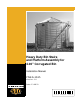
Heavy Duty Bin Stairs and Platform Assembly for 4.00" Corrugated Bin Installation Manual PNEG-1615 Version: 1.
PNEG-1615 Heavy Duty Bin Stairs and Platform Assembly for 4.
Table of Contents Contents Chapter 1 Safety .....................................................................................................................................................4 Safety Guidelines .................................................................................................................................. 4 Safety Instructions .................................................................................................................................
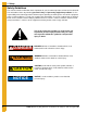
1. Safety Safety Guidelines This manual contains information that is important for you, the owner/operator, to know and understand. This information relates to protecting personal safety and preventing equipment problems. It is the responsibility of the owner/operator to inform anyone operating or working in the area of this equipment of these safety guidelines. To help you recognize this information, we use the symbols that are defined below. Please read the manual and pay attention to these sections.
1. Safety Safety Instructions Our foremost concern is your safety and the safety of others associated with this equipment. We want to keep you as a customer. This manual is to help you understand safe operating procedures and some problems that may be encountered by the operator and other personnel. As owner and/or operator, it is your responsibility to know what requirements, hazards, and precautions exist, and to inform all personnel associated with the equipment or in the area.
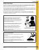
1. Safety Prepare for Emergencies Be prepared if fire starts. Keep a first aid kit and fire extinguisher handy. Keep emergency numbers for doctors, ambulance service, hospital, and fire department near your telephone. Keep Emergency Equipment Quickly Accessible Wear Protective Clothing Wear close-fitting clothing and safety equipment appropriate to the job. Eye Protection Remove all jewelry. Gloves Tie long hair up and back. Wear safety glasses at all times to protect eyes from debris.
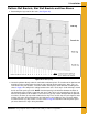
2. Installation Platform Wall Brackets, Stair Wall Brackets and Knee Braces 1. Determining the layout of the bin stairs. (See Figure 2A.) Figure 2A Bin Bolt Spacing 2. Locate the platform directly under the roof ladder and manway hole. The location of the platform and manhole must be pre-determined so that the stairs will not interfere with auger, doors, fans, etc. To determine the stair locations, count the number of bolt spaces around the bin according to the chart on Page 8.
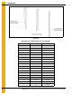
2. Installation Figure 2B Bolt Spaces around Bin with 4.00" Corrugation 8 Rings Bolt Spaces Inches 4 20 187-1/2 5 25 234-3/8 6 31 290-5/8 7 36 337-1/2 8 42 393-3/4 9 47 440-5/8 10 53 496-7/8 11 58 543-3/4 12 64 600.000 13 69 646-7/8 14 75 703-1/8 15 80 750.000 16 86 806-1/4 17 91 853-1/8 18 97 909-3/8 19 102 956-1/4 20 108 1012-1/2 21 113 1059-3/8 PNEG-1615 Heavy Duty Bin Stairs and Platform Assembly for 4.
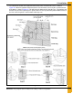
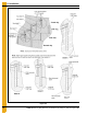
2. Installation 3. The attachment location of the platform wall bracket to the first horizontal seam is shown in Figure 2C. Attach the platform wall bracket to the first horizontal seam using the second hole from the bottom as shown in Figure 2C. This will locate the platform 16" below the eave. The platform wall brackets are placed six (6) bolt spaces apart or 56-1/4". Loosely attach the platform wall brackets to the first seam using 5/16" x 3/4" bin bolts and flange nuts.
2. Installation Figure 2D 10 PNEG-1615 Heavy Duty Bin Stairs and Platform Assembly for 4.
2. Installation Figure 2E 4. Field drill two (2) holes per platform bracket as shown and use 5/16" x 3/4" bin bolts and flange nuts at the top connection points. The bottom connection points will also be used for the platform knee brace during platform installation. 5. Four (4) step sections will be placed following the placement of the platform. Therefore, the first stair wall bracket is placed four (4) bolt spaces around the bin on the second ring as shown in Figure 2C on Page 9.
2. Installation Assembling the Platform 1. Figure 2F shows the assembly of the platform supports. Use 5/16" hardware at all the connection points. Note the center floor brace (LS-6701) is offset from the center of the platform. (The bin wall is hidden for clarity.) Figure 2F 2. Figure 2G shows the assembly of the platform floor, toe plate and vertical angles. This must all be assembled at the same time using 5/16" hardware. Note the color codes, placement and orientation of the platform vertical angles.
2. Installation 3. Figure 2H shows the assembly of the platform handrails. These must also be attached using 5/16" hardware. Figure 2H Assembling the Stairs 1. Figure 2I shows the assembly of the HD stairs. The ends of the steps are bolted under and behind the step using 5/16" x 3/4" truss head bolt and nut. Figure 2I PNEG-1615 Heavy Duty Bin Stairs and Platform Assembly for 4.
2. Installation 2. Figure 2J shows the assembly of the stair bracing. As shown before in Figure 2C on Page 9, the first vertical wall bracket will be located four (4) bolt spaces or 37-1/2" around the bin. 3/8" Hardware is used at the four (4) connection points as shown. The outer two (2) mounting holes on the side and the outer middle hole on the top of the horizontal wall bracket will be used to attach the step as shown in Figure 2K.
2. Installation 3. Figure 2L shows the assembly of the top four (4) steps. Use 5/16" hardware at the connection points and refer to Figure 2M, Figure 2N, Figure 2O and Figure 2M on Pages 15-16 for hole and slot usage for the size bin. These illustrations will show how to align the holes on the attachment tabs with the slots of the next step. Attach the tie straps on the inside and outside of the steps as shown in Figure 2L. Use standard steps (Refer to Figure 2I on Page 13 for assembly instructions.
2. Installation Bin diameters 60' to 72' Figure 2N Bin diameters 75' to 78' Figure 2O Bin diameters 90' to 105' Figure 2P 16 PNEG-1615 Heavy Duty Bin Stairs and Platform Assembly for 4.
2. Installation 4. Figure 2Q shows the addition of the next step stair section. The fifth step attaches to the wall bracket as shown in Figure 2K on Page 14. Use the holes and slots to connect the stairs as shown in the Figure 2M, Figure 2N, Figure 2O and Figure 2P on Pages 15-16. Continue attaching tie straps on the inside and outside of the steps. Continue with standard four (4) step packages (Refer to Figure 2I on Page 13.) Figure 2Q PNEG-1615 Heavy Duty Bin Stairs and Platform Assembly for 4.
2. Installation 5/16" x 3/4" Truss head bolts Horizontal bracket (LDR-4083) Figure 2R Horizontal Bracket to Step 5/16" x 3/4" Truss head bolt and nut Attachment tab Tie strap (STR1078) Figure 2S Brace Strap Connection 5. Continue adding four (4) step sections until you have reached the bottom of the bin. Each of the next wall brackets will be placed 32" lower and four (4) bolt spaces or 37-1/2" around the bin farther than the previous bracket.
2. Installation Adding the Handrails 1. Figure 2T shows the addition of the handrail posts. Use two (2) 3/8" x 1" flange bolts and nuts to attach the handrail post to the horizontal wall bracket. Make sure the post is plumb before tightening the bolts. Figure 2T PNEG-1615 Heavy Duty Bin Stairs and Platform Assembly for 4.
2. Installation Handrail post (LDR-4085) Two (2) 3/8" x 1" Flange head bolts and nuts Figure 2U Handrail Post Connection to Horizontal Wall Bracket 2. Begin installation with the upper handrail. The handrail for the first two (2) steps should be loosely bolted to the first post and checked to ensure it is the right length. Excess length of the narrow end of the handrail may need to be cut off and a new hole drilled for connection to the top platform handrail. Use 5/16" x 1-1/4" bolts at the connections.
2. Installation Four (4) step handrail (STR1077) 5/16" x 1-1/4" Bolt and nut Figure 2W Upper Handrail Connection 3. After installing the top handrails, the intermediate handrails can be put into place. They will use the top hole in the middle of the handrail post with 5/16" x 1-1/4" bolts and nut. (See Figure 2T on Page 19.) The large tube should be placed on the upper handrail post and the small tube should be slid into it and placed on the lower handrail post.
2. Installation Assembling Intermediate Platform (Optional Package #STR1143) 1. The intermediate platform wall brackets and bordering stair section wall brackets should be arranged as shown in Figure 2Y. The first platform bracket should be placed three (3) bolt spaces around the bin and 32" below the previous stair wall bracket. The next platform bracket should be placed six (6) bolt spaces around the bin at the same height as the previous platform bracket.
2. Installation 3. Figure 2AA shows the assembly of the platform floor, toe plate and vertical angles. This must all be assembled at the same time using 5/16" hardware. Note the orientation of the vertical angles. Figure 2AA 4. Figure 2AB shows the assembly of the platform handrails. These must also be attached using 5/16" hardware. Figure 2AB PNEG-1615 Heavy Duty Bin Stairs and Platform Assembly for 4.
2. Installation 5. Figure 2AC shows the addition of the steps. Three (3) steps will be located above the rest platform and four (4) are located below the rest platform. The first step above the platform will need to be securely attached to the handrail and toe plate. A field drilled 3/8" hole will need to be placed in the handrail in line with the slot in the step. Self-tapping screws will need to be placed in the top of the step for connection to the toe plate. Figure 2AC 6.
3. Warranty GSI Group, LLC Limited Warranty The GSI Group, LLC (“GSI”) warrants products which it manufactures to be free of defects in materials and workmanship under normal usage and conditions for a period of 12 months after sale to the original end-user or if a foreign sale, 14 months from arrival at port of discharge, whichever is earlier.
This equipment shall be installed in accordance with the current installation codes and applicable regulations, which should be carefully followed in all cases. Authorities having jurisdiction should be consulted before installations are made. GSI Group 1004 E. Illinois St. Assumption, IL 62510-0020 Phone: 1-217-226-4421 Fax: 1-217-226-4420 www.gsiag.