Ladder, Safety Cage and Platform Assembly for GSI Hopper Tanks Installation Manual PNEG-1451 Date: 03-17-11 PNEG-1451
PNEG-1451 Ladder, Safety Cage and Platform for Hopper Tanks
Table of Contents Contents Chapter 1 Introduction ..........................................................................................................................................5 Chapter 2 Safety .....................................................................................................................................................6 Safety Guidelines ..................................................................................................................................
Table of Contents Intermediate Starter Bracket and Ladder Assembly with Safety Cage ............................................... 54 Intermediate and Base Safety Cage Hoop Assembly ......................................................................... 55 Base Platform Mounting Angle Installation ......................................................................................... 56 Location of Field Drilled Holes for Base Ladder Starter Brackets ...................................................
1. Introduction READ THIS MANUAL carefully to learn how to properly use and install equipment. Failure to do so could result in personal injury or equipment damage. INSPECT the shipment immediately upon arrival. The customer is responsible for ensuring that all quantities are correct. The customer should report and note any damage or shortage on the bill of lading to justify their claim to the transport company.
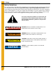
2. Safety Safety Guidelines This manual contains information that is important for you, the owner/operator, to know and understand. This information relates to protecting personal safety and preventing equipment problems. It is the responsibility of the owner/operator to inform anyone operating or working in the area of this equipment of these safety guidelines. To help you recognize this information, we use the symbols that are defined below. Please read the manual and pay attention to these sections.
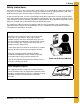
2. Safety Safety Instructions Our foremost concern is your safety and the safety of others associated with this equipment. We want to keep you as a customer. This manual is to help you understand safe operating procedures and some problems which may be encountered by the operator and other personnel. As owner and/or operator, it is your responsibility to know what requirements, hazards and precautions exist, and to inform all personnel associated with the equipment or in the area.
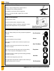
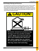
2. Safety Stay Clear of Hoisted Equipment Always use proper lifting/hoisting equipment when assembling or disassembling equipment. Do not walk or stand under hoisted equipment. Always use sturdy and stable supports when needed for installation. Crush Hazard Prepare for Emergencies Be prepared if fire starts. Keep a first aid kit and fire extinguisher handy. Keep emergency numbers for doctors, ambulance service, hospital and fire department near your telephone.
3. Safety Decals Roof Damage Warning and Disclaimer The manufacturer does not warrant any roof damage caused by excessive vacuum or internal pressure from fans or other air moving systems. Adequate ventilation and/or “makeup air” devices should be provided for all powered air handling systems. The manufacturer does not recommend the use of downward flow systems (suction). Severe roof damage can result from any blockage of air passages.
3. Safety Decals ATTENTION: The decal shown below should be present on the outside of the door cover of the 2 ring on the 24" porthole door cover, and on the roof manway cover. If a decal has been damaged or is missing in any of these locations, contact the manufacturer for a free replacement decal. GSI Decals 1004 E. Illinois St. Assumption, IL. 62510 Phone: 1-217-226-4421 Rotating flighting will kill or dismember. Flowing material will trap and suffocate. Crusted material will collapse and suffocate.
3. Safety Decals ATTENTION: The decal shown below should be present on the outside of the door cover of the 2 ring on the 24" porthole door cover, and on the roof manway cover. If a decal has been damaged or is missing in any of these locations, contact the manufacturer for a free replacement decal. GSI Decals 1004 E. Illinois St. Assumption, IL. 62510 Phone: 1-217-226-4421 WARNIN DON’T DO UNLOADING INSTRUCTIONS: 1. Use CENTER FLOOR OUTLET ONLY until NO grain remains above this outlet. 2.
4. General Detail Information Extension Rail Installation All ladder systems that include a safety cage must also include ladder extension rails attached to the top four foot (4') ladder section. Start by bolting the spacer brackets through the top and bottom set of holes in the top ladder section. Then, attach the extension rails to the spacer brackets as shown in Figure 4A. When installed correctly, the bottom of the extension rail should be flush with the bottom of the top ladder section.
4. General Detail Information Ladder Section Assembly Two (2) splice plates (LDR-4317) are required to attach each ladder section. The head of the bolt should be to the inside of the ladder with the splice plate on the outside as shown in Figure 4B. Use 5/16" x 3/4" bolts for all connections. NOTE: With most installations, the last ladder section installed to reach the ground, the base or the intermediate platform should be cut to fit.
4.
4. General Detail Information Extension Angle Hole Detail Figure 4D NOTE: Platform and platform support shown for reference only. See platform assembly detail on Page 47 for complete installation instructions for these parts.
4. General Detail Information Cage Hoop Bracket Assembly NOTE: Leave bolt loose until cage hoop half has been attached.
4.
NOTES 18 PNEG-1451 Ladder, Safety Cage and Platform for Hopper Tanks
® 2.
5. 2.66" Corrugated Commercial Hopper Tank 4-9 Rings 2.66" Commercial Hopper Tank (NCHT) Ladder and Platform Layout 4-9 Rings 32" Safety cage sections (See note on page 21.) Figure 5A 9 Rings See Page 21 for platform locations and section listings.
5. 2.66" Corrugated Commercial Hopper Tank 4-9 Rings Ladder, Safety Cage and Platform Location Chart For Section A, find the proper ring grain bin and use the number of ladders and safety cages indicated. See Chart below (Section A). For Section B, find the proper diameter grain bin and hopper slope, then use the number of ladders and safety cages indicated. See Chart below (Section B).
5. 2.66" Corrugated Commercial Hopper Tank 4-9 Rings NCHT Ladder, Safety Cage and Platform Instructions 4-9 Rings All grain bin packages, from 4 ring to 9 ring and 12' to 35' diameter, contain the correct components for assembly. Read and follow the complete instructions for correct placement of parts. Be sure and use the charts to determine the appropriate number and size parts to be used based upon the number of rings in the bin. Failure to do so may result in an improper fit or shortage of parts.
5. 2.66" Corrugated Commercial Hopper Tank 4-9 Rings Location of Field Drilled Holes for Eave Ladder Starter Brackets The starter brackets must be located directly below the roof ladder. Before the starter brackets can be installed, two (2) 3/8" holes must be field drilled 2.66" below and directly in line with the top row of pre-punched horizontal holes.
5. 2.66" Corrugated Commercial Hopper Tank 4-9 Rings Eave Starter Bracket and Ladder Assembly with Safety Cage Once the two (2) 3/8" holes have been field drilled, attach the starter brackets to the sidewall as shown in Figure 5C. Check the top ladder section to make sure the ladder rung dimples are to the top. Attach starter brackets to the top of the ladder. See Figure 4B on Page 13 for the proper installation of additional ladder sections required.
5. 2.
5. 2.66" Corrugated Commercial Hopper Tank 4-9 Rings Eave Adjustable Braces The eave adjustable braces must be attached at this time. An eave adjustable brace is comprised of one large diameter tube and two (2) smaller diameter tubes. (See Figure 5F.) Slide the smaller tubes inside the larger tubes and attach one smaller tube to the top of the ladder extension rail. Adjust the other smaller tube so the bottom of the flattened tube reaches the roof panel.
5. 2.66" Corrugated Commercial Hopper Tank 4-9 Rings Eave Platform Mounting Angle Installation Figure 5H shows the location of the platform mounting angles. Each angle must be mounted starting 4" below the top horizontal seam of the second ring with the first mounting angle offset 9-3/8" from the right hand starter bracket. The second mounting angle must be located 56-1/4" from the first mounting angle. The dimensions and locations of these angles are critical for proper fit of all parts.
5. 2.66" Corrugated Commercial Hopper Tank 4-9 Rings Right Hand Platform and Platform Support Assembly NOTE: Mount the platform supports on the bin first. Next, assemble the platform floor onto the support frame. Do not tighten platform support to floor brace bolts until the floor and toe plates are secure. Assemble the platform support frame using 5/16" x 3/4" truss head bolts and nuts. (See Figure 5I.
5. 2.66" Corrugated Commercial Hopper Tank 4-9 Rings Eave Safety Cage Hoop Assembly Before attaching any pieces to the ladders or platform, some pre-assembly is required. Attach two (2) safety cage brackets to the 8' extension rail and one safety cage bracket to the second 4' ladder section as shown in Figure 5K. Bolt the safety cage hoop adjuster plates onto the extension angle as shown in Figure 5K.
5. 2.66" Corrugated Commercial Hopper Tank 4-9 Rings Adapter Assembly Detail Figure 5L Connection Detail Use Figure 5M to determine the proper holes to use when attaching the hoop adapter to the adjuster plate.
5. 2.66" Corrugated Commercial Hopper Tank 4-9 Rings Vertical Supports After all three (3) hoop assemblies are in place, attach the 48" vertical supports from hoop assembly to hoop assembly, as shown in Figure 5N. This requires ten (10) supports, five (5) between each set of hoops. The second set of vertical supports must be bent at the flat area to allow for the tapering of the bottom hoop assembly. Use 5/16" x 3/4" bolts (unless otherwise noted) with the head of the bolt to the inside of the safety cage.
5. 2.
5. 2.66" Corrugated Commercial Hopper Tank 4-9 Rings Left Hand Platform and Platform Support Assembly NOTE: Mount the platform mounting angles on the columns first. Next, assemble the platform floor onto the support frame. Do not tighten platform support to floor brace bolts until the floor and toe plates are secure. Assemble the platform support frame using 5/16" x 3/4" truss head bolts and nuts.
5. 2.66" Corrugated Commercial Hopper Tank 4-9 Rings Access Door Safety Cage Hoop Assembly Before attaching any pieces to the ladder or platform, some pre-assembly is required. Attach the safety cage brackets to the ladder section. (See Figure 5K on Page 29.) Bolt the safety cage hoop adjuster plates onto the extension angle as shown in Figure 5T. For the middle hoop assembly, bolt the safety cage hoop adapters and safety cage hoop half together using the proper holes, based upon the bin diameter.
5. 2.66" Corrugated Commercial Hopper Tank 4-9 Rings 24"-48" Safety Cage Bell Sections Attach the vertical supports to the hoop half assembly from the final safety cage installation using 5/16" x 3/4" bolts and nuts (with the heads on the inside of the cage). Assemble the special bell safety cage hoop halves and attach to other end of vertical supports. The vertical support must be bent at the flat area to allow for the angle of the bell section.
5. 2.66" Corrugated Commercial Hopper Tank 4-9 Rings Ladder Support Detail The ladder must be secured to the hopper support columns with ladder standoff brackets using support channels and ladder brackets as shown in Figure 5W. Figure 5W 36 Tank Diameter Hopper Slope No.
® 2.
6. 2.66" Corrugated Commercial Hopper Tank 10-22 Rings 2.
6. 2.66" Corrugated Commercial Hopper Tank 10-22 Rings Ladder, Safety Cage and Platform Location Chart For Section A through C, find the proper ring grain bin and use the number of ladders and safety cages as shown in the Chart below. For Section D, find the proper diameter grain bin and hopper slope and use the number of ladders and safety cages as shown in the Chart on Page 41.
6. 2.66" Corrugated Commercial Hopper Tank 10-22 Rings NCHT Ladder, Safety Cage and Platform Instructions 10-22 Rings All grain bin packages, from 10 ring to 22 ring and 12' to 36' diameter, contain the correct components for assembly. Be sure and use the charts to determine the appropriate number and size parts to be used based upon the number of rings in the bin. Read and follow the complete instructions for correct placement of parts. Failure to do so may result in an improper fit or shortage of parts.
6. 2.66" Corrugated Commercial Hopper Tank 10-22 Rings Eave Starter Bracket and Ladder Assembly with Safety Cage Once the two (2) 3/8" holes have been field drilled, attach the starter brackets to the sidewall as shown in Figure 6D. Check the top ladder section to make sure the ladder rung dimples are to the top. Attach starter brackets to the top of the ladder. It will be necessary to field drill a 3/8" hole in the ladder section for the starter bracket as well. (See Figure 6F on Page 44.
6. 2.66" Corrugated Commercial Hopper Tank 10-22 Rings Figure 6E NOTE: Refer to Figure 6D on Page 43 for proper location of ladder starter brackets.
6. 2.66" Corrugated Commercial Hopper Tank 10-22 Rings Eave Adjustable Braces The eave adjustable braces must be attached at this time. An eave adjustable brace is comprised of one large diameter tube and two (2) smaller tubes. (See Figure 6G.) Slide the smaller tubes inside the larger tubes and attach one smaller tube to the top of the ladder extension rail. Adjust the other smaller tube so the bottom of the flattened tube reaches the roof panel.
6. 2.66" Corrugated Commercial Hopper Tank 10-22 Rings Eave Platform Mounting Angle Installation Figure 6I shows the location of the platform mounting angles. Each angle must be mounted starting 4" below the top horizontal seam of the second ring with the first mounting angle offset 9-3/8" from the right hand starter bracket. The second mounting angle must be located 56-1/4" from the first mounting angle. The dimensions and locations of these angles are critical for proper fit of all parts.
6. 2.66" Corrugated Commercial Hopper Tank 10-22 Rings Right Hand Platform and Platform Support Assembly NOTE: Mount the platform supports on the bin first. Next, assemble the platform floor onto the support frame. Do not tighten platform support to floor brace bolts until the floor and toe plates are secure. Assemble the platform support frame using 5/16" x 3/4" truss head bolts and nuts. (See Figure 5I on Page 28.
6. 2.66" Corrugated Commercial Hopper Tank 10-22 Rings Eave Safety Cage Hoop Assembly Before attaching any pieces to the ladders or platform, some pre-assembly is required. Attach two (2) safety cage brackets to the 8' extension rail and one safety cage bracket to the second 4' ladder section as shown in Figure 6L. Bolt the safety cage hoop adjuster plates onto the extension angle as shown in Figure 6L.
6. 2.66" Corrugated Commercial Hopper Tank 10-22 Rings Adapter Assembly Detail Figure 6M 18' Diameter through 21' Diameter Bins Connection Detail Use Figure 6N to determine the proper holes to use when attaching the hoop adapter to the adjuster plate.
6. 2.66" Corrugated Commercial Hopper Tank 10-22 Rings Vertical Supports After all three (3) hoop assemblies are in place, attach the 48" vertical supports from hoop assembly to hoop assembly, as shown in Figure 6O. This requires ten (10) supports, five (5) between each set of hoops. The second set of vertical supports must be bent at the flat area to allow for the tapering of the bottom hoop assembly.
6. 2.66" Corrugated Commercial Hopper Tank 10-22 Rings 24"-48" Safety Cage Bell Sections Attach the vertical supports to the hoop half assembly from the final safety cage installation using 5/16" x 3/4" bolts and nuts (with the heads on the inside of the cage). Assemble the special bell safety cage hoop halves and attach to other end of vertical supports. The vertical support will have to be bent at the flat area to allow for the angle of the bell section.
6. 2.66" Corrugated Commercial Hopper Tank 10-22 Rings Intermediate Platform Mounting Angle Installation For bins with 18-22 rings, an intermediate platform is required. Figure 6S shows the location of the intermediate platform mounting angles. Each angle must be mounted starting 4" below the top horizontal seam of the ring specified in the Chart on Page 41, with the first mounting angle directly in line with the left hand eave mounting angle.
6. 2.66" Corrugated Commercial Hopper Tank 10-22 Rings Location of Field Drilled Holes for Intermediate Ladder Starter Brackets Before installing the starter brackets, field drill two (2) 3/8" holes located 2.66" below and directly in line with the top horizontal seam holes located in the third ring up from the intermediate platform mounting angles.
6. 2.66" Corrugated Commercial Hopper Tank 10-22 Rings Intermediate Starter Bracket and Ladder Assembly with Safety Cage After drilling the two (2) 3/8" holes, attach the starter brackets to the sidewall as shown in Figure 6U. Check the top ladder section to make sure the ladder rung dimples are to the top surface and attach to the starter brackets using the holes located 1" from the top of the ladder. See general detail information on Page 12 for proper installation of additional ladder sections required.
6. 2.66" Corrugated Commercial Hopper Tank 10-22 Rings Intermediate and Base Safety Cage Hoop Assembly Before attaching any pieces to the ladders or platform, some pre-assembly is required. Attach the safety cage brackets to the ladder section. (See general detail information on Page 12.) Bolt the safety cage hoop adjuster plates onto the extension angle as shown in Figure 6V.
6. 2.66" Corrugated Commercial Hopper Tank 10-22 Rings Base Platform Mounting Angle Installation Figure 6W shows the location of the base platform mounting angles. Each angle must be mounted starting 4" below the top horizontal seam of the third ring from the bottom of the tank with the first mounting angle directly in line with the left hand eave or intermediate mounting angle (if applicable). The second mounting angle must be located 56-1/4" to the left of the first mounting angle.
6. 2.66" Corrugated Commercial Hopper Tank 10-22 Rings Location of Field Drilled Holes for Base Ladder Starter Brackets Before installing the starter brackets, field drill two (2) 3/8" holes 2.66" below and directly in line with the top horizontal seam holes located in the sixth ring from the bottom of the tank. The first hole, for the right hand starter bracket, must be located 9-3/8" from the center of the left hand base platform mounting angle to the center of the hole.
6. 2.66" Corrugated Commercial Hopper Tank 10-22 Rings Base Starter Bracket and Ladder Assembly with Safety Cage Once the two (2) 3/8" holes have been field drilled, attach the starter brackets to the sidewall as shown in Figure 6Y. Check the top ladder section to make sure the ladder rung dimples are to the top. Attach to the starter brackets using the holes located 1" from the top of the ladder. It will also be necessary to field drill a 3/8" hole in the ladder section.
6. 2.
6. 2.66" Corrugated Commercial Hopper Tank 10-22 Rings Left Hand Platform and Platform Support Assembly NOTE: Mount the platform mounting angles supports on the column first. Next, assemble the platform floor onto the support frame. Do not tighten platform support to floor brace bolts until the floor and toe plates are secure. Assemble the platform support frame using 5/16" x 3/4" truss head bolts and nuts.
6. 2.66" Corrugated Commercial Hopper Tank 10-22 Rings Access Door Safety Cage Hoop Assembly Before attaching any pieces to the ladder or platform, some pre-assembly is required. Attach the safety cage brackets to the ladder section. (See general detail information on Page 12 for proper installation instructions.) Bolt the safety cage hoop adjuster plates onto the extension angle as shown in Figure 6AC.
6. 2.66" Corrugated Commercial Hopper Tank 10-22 Rings Ladder Support Detail The ladder must be secured to the hopper support columns with ladder standoff brackets using support channels and ladder brackets as shown in Figure 6AD.
® 4.
7. 4.00" Corrugation Farm Commercial Hopper Tanks (FCHT) 4-6 Rings 4.00" Farm Commercial Hopper Tank Ladder and Platform Layout 4-6 Rings 44" Safety cage see note below. Figure 7A 6 Rings NOTE: The 44" safety cage sections must be installed in Section A of the ladder system. DO NOT install the 44" verticals in the eave or access door safety cage hoop assembly.
7. 4.00" Corrugation Farm Commercial Hopper Tanks (FCHT) 4-6 Rings Ladder, Safety Cage and Platform Location Chart For Section A, find the proper ring grain bin and use the number of ladders and safety cages. See Chart below (Section A). For Section B, find the proper diameter grain bin and hopper slope and use the number of ladders and safety cages. See Chart below (Section B).
7. 4.00" Corrugation Farm Commercial Hopper Tanks (FCHT) 4-6 Rings FCHT Ladder, Safety Cage and Platform Instructions 4-6 Rings All grain bin packages, from 4 ring to 6 ring and 18' to 24' diameter, contain the correct components for assembly. Read and follow the complete instructions for correct placement of parts. Be sure and use the charts to determine the appropriate number and size parts to be used based upon the number of rings in the bin.
7. 4.00" Corrugation Farm Commercial Hopper Tanks (FCHT) 4-6 Rings Location of Field Drilled Holes for Eave Ladder Starter Brackets The starter brackets must be located directly below the roof ladder. Before the starter brackets can be installed, two (2) 3/8" holes must be drilled 4" below and directly in line with the top row of pre-punched horizontal holes. The first hole, for the left hand starter bracket, must be located 9-3/8" from the center of the stiffener to the center of the hole.
7. 4.00" Corrugation Farm Commercial Hopper Tanks (FCHT) 4-6 Rings Eave Starter Bracket and Ladder Assembly with Safety Cage Once the two (2) 3/8" holes have been field drilled, attach the starter brackets to the sidewall as shown in Figure 7C. Check the top ladder section to make sure the ladder rung dimples are to the top. Attach starter brackets to the top of the ladder. It will also be necessary to field drill a 3/8" hole on the ladder section for the starter bracket.
7. 4.
7. 4.00" Corrugation Farm Commercial Hopper Tanks (FCHT) 4-6 Rings Eave Adjustable Braces The eave adjustable braces must be attached at this time. An eave adjustable brace is comprised of one larger diameter tube and two (2) smaller tubes. (See Figure 7F.) Slip the smaller tubes inside the larger tubes and attach one smaller tube to the top of the ladder extension rail. Adjust the other smaller tube so the bottom of the flattened tube reaches the roof panel.
7. 4.00" Corrugation Farm Commercial Hopper Tanks (FCHT) 4-6 Rings Eave Platform Mounting Angle Installation Figure 7H shows the location of the platform mounting angles. Each angle must be mounted starting 8" above the top horizontal seam of the second ring with the first mounting angle offset 9-3/8" from the right hand starter bracket. The second mounting angle must be located 56-1/4" from the first mounting angle. The dimensions and locations of these angles are critical for proper fit of all parts.
7. 4.00" Corrugation Farm Commercial Hopper Tanks (FCHT) 4-6 Rings Right Hand Platform and Platform Support Assembly NOTE: Mount the platform supports on the bin first. Next, assemble the platform floor onto the support frame. Do not tighten platform support to floor brace bolts until the floor and toe plates are secure. Assemble the platform support frame using 5/16" x 3/4" truss head bolts and nuts.
7. 4.00" Corrugation Farm Commercial Hopper Tanks (FCHT) 4-6 Rings Eave Safety Cage Hoop Assembly Before attaching any pieces to the ladders or platform, some pre-assembly is required. Attach two (2) safety cage brackets to the 8' extension rail and one safety cage bracket to the second 4' ladder section as shown in Figure 7K. (See Page 48 for assembly details.) Bolt the safety cage hoop adjuster plates onto the extension angle as shown.
7. 4.00" Corrugation Farm Commercial Hopper Tanks (FCHT) 4-6 Rings Adapter Assembly Detail Figure 7L 18' Diameter through 21' Diameter Bins Connection Detail Use Figure 7M to determine the proper holes to use when attaching the hoop adapter to the adjuster plate.
7. 4.00" Corrugation Farm Commercial Hopper Tanks (FCHT) 4-6 Rings Vertical Supports After all three (3) hoop assemblies are in place, attach the 48" vertical supports from hoop assembly to hoop assembly, as shown in Figure 7N. This requires ten (10) supports, five (5) between each set of hoops. The second set of vertical supports must be bent at the flat area to allow for the tapering of the bottom hoop assembly.
7. 4.00" Corrugation Farm Commercial Hopper Tanks (FCHT) 4-6 Rings Access Door Platform Mounting Angle Installation Figure 7Q shows the location of the access door platform mounting angles. Each angle must be mounted starting 16" above the top horizontal seam of the bottom ring and installed in the stiffeners located on each side of the access door. When installed correctly, these angles should be offset from the eave platform mounting angles 37-1/2". Pay careful attention when installing these angles.
7. 4.00" Corrugation Farm Commercial Hopper Tanks (FCHT) 4-6 Rings Left Hand Platform and Platform Support Assembly NOTE: Mount the platform supports on the bin first. Next, assemble the platform floor onto the support frame. Do not tighten platform support to floor brace bolts until the floor and toe plates are secure. Assemble the platform support frame using 5/16" x 3/4" truss head bolts and nuts.
7. 4.00" Corrugation Farm Commercial Hopper Tanks (FCHT) 4-6 Rings Access Door Safety Cage Hoop Assembly Before attaching any pieces to the ladder or platform, some pre-assembly is required. Attach the safety cage brackets to the ladder section. (See general detail information on Page 12 for proper installation instructions.) Bolt the safety cage hoop adjuster plates onto the extension angle as shown in Figure 7T.
7. 4.00" Corrugation Farm Commercial Hopper Tanks (FCHT) 4-6 Rings 24"-48" Safety Cage Bell Sections Attach the vertical supports to the hoop half assembly from the safety cage installation using 5/16" x 3/4" bolts and nuts (with the heads on the inside of the cage). Assemble the special bell safety cage hoop halves and attach to other end of vertical supports. The vertical supports will have to be bent at the flat area to allow for the angle of the bell section.
7. 4.00" Corrugation Farm Commercial Hopper Tanks (FCHT) 4-6 Rings Ladder Support Detail The ladder must be secured to the hopper support columns with ladder standoff brackets using support channels and ladder brackets as shown in Figure 7W. Figure 7W Tank Diameter Hopper Slope No.
® 4.
8. 4.00" Corrugation Farm Commercial Hopper Tank (FCHT) 7-9 Rings 4.00" Farm Commercial Hopper Tank (FCHT) Ladder and Platform Layout Ladder, Safety Cage and Platform Location Chart For Section A, find the proper ring grain bin and use the number of ladders and safety cages indicated. See Chart below (Section A). For Section B, find the proper diameter grain bin and hopper slope and use the number of ladders and safety cages indicated. See Chart below (Section B).
8. 4.00" Corrugation Farm Commercial Hopper Tank (FCHT) 7-9 Rings FCHT Ladder, Safety Cage and Platform Instructions 7-9 Rings All grain bin packages, from 7 ring to 9 ring and 18' to 24' diameter, contain the correct components for assembly. Read and follow the complete instructions for correct placement of parts. Be sure and use the charts to determine the appropriate number and size parts to be used based upon the number of rings in the bin.
8. 4.00" Corrugation Farm Commercial Hopper Tank (FCHT) 7-9 Rings Eave Starter Bracket and Ladder Assembly with Safety Cage Once the two (2) 3/8" holes have been field drilled, attach the starter brackets to the sidewall as shown in Figure 8C. Check the top ladder section to make sure the ladder rung dimples are to the top. Attach starter brackets to the top of the ladder. See general detail information on Page 12 for the proper installation of additional ladder sections required.
8. 4.
8. 4.00" Corrugation Farm Commercial Hopper Tank (FCHT) 7-9 Rings Eave Adjustable Braces The eave adjustable braces must be attached at this time. An eave adjustable brace is comprised of one larger diameter tube and two (2) smaller tubes. (See Figure 8F.) Slip the smaller tubes inside the larger tubes and attach one smaller tube to the top of the ladder extension rail. Adjust the other smaller tube so the bottom of the flattened tube reaches the roof panel.
8. 4.00" Corrugation Farm Commercial Hopper Tank (FCHT) 7-9 Rings Eave Platform Mounting Angle Installation Figure 8H shows the location of the platform mounting angles. Each angle must be mounted starting 8" above the top horizontal seam of the second ring with the first mounting angle offset 9-3/8" from the right hand starter bracket. The second mounting angle must be located 56-1/4" from the first mounting angle. The dimensions and locations of these angles are critical for proper fit of all parts.
8. 4.00" Corrugation Farm Commercial Hopper Tank (FCHT) 7-9 Rings Eave Platform and Platform Support Assembly NOTE: Mount the platform mounting angles on the bin first. Next, assemble the platform floor onto the support frame. Do not tighten platform support to floor brace bolts until the floor and toe plates are secure. Assemble the platform support frame using 5/16" x 3/4" truss head bolts and nuts.
8. 4.00" Corrugation Farm Commercial Hopper Tank (FCHT) 7-9 Rings Eave Safety Cage Hoop Assembly Before attaching any pieces to the ladders or platform, some pre-assembly is required. Attach two (2) safety cage brackets to the 8' extension rail and one safety cage bracket to the second 4' ladder section as shown in Figure 8K. (See Page 48 for assembly details.) Bolt the safety cage hoop adjuster plates onto the extension angle as shown in Figure 8K.
8. 4.00" Corrugation Farm Commercial Hopper Tank (FCHT) 7-9 Rings Adapter Assembly Detail Figure 8L 18' Diameter through 21' Diameter Bins Connection Detail Use Figure 8M to determine the proper holes to use when attaching the hoop adapter to the adjuster plate.
8. 4.00" Corrugation Farm Commercial Hopper Tank (FCHT) 7-9 Rings Vertical Supports After all three (3) hoop assemblies are in place, you may attach the 48" vertical supports from hoop assembly to hoop assembly, as shown in Figure 8N. This requires ten (10) supports, five (5) between each set of hoops. The second set of vertical supports must be bent at the flat area to allow for the tapering of the bottom hoop assembly.
8. 4.00" Corrugation Farm Commercial Hopper Tank (FCHT) 7-9 Rings 24"-48" Safety Cage Bell Sections Attach the vertical supports to the hoop half assembly from the final safety cage installation using 5/16" x 3/4" bolts and nuts (with the heads on the inside of the cage). Assemble the special bell safety cage hoop halves and attach to other end of vertical supports. The vertical support must be bent at the flat area to allow for the angle of the bell section.
8. 4.00" Corrugation Farm Commercial Hopper Tank (FCHT) 7-9 Rings Access Door/Base Platform Mounting Angle Installation Figure 8R shows the location of the access door platform mounting angles. All four (4) angles must be mounted starting 16" above the top horizontal seam of the bottom ring with the first mounting angle directly in line with the left hand eave mounting angle. The second mounting angle must be located 56-1/4" to the left of the first mounting angle.
8. 4.00" Corrugation Farm Commercial Hopper Tank (FCHT) 7-9 Rings Location of Field Drilled Holes for Base/Access Door Ladder Starter Brackets Before the starter brackets can be installed, two (2) 3/8" holes must be drilled. The holes must be located 4" below and directly in line with the top horizontal seam holes located in the 3rd ring from the bottom of the tank.
8. 4.00" Corrugation Farm Commercial Hopper Tank (FCHT) 7-9 Rings Base/Access Door Starter Bracket and Ladder Assembly with Safety Cage Once the two (2) 3/8" holes have been drilled, attach the starter brackets to the sidewall as shown in Figure 8T. Check the top ladder section to make sure the ladder rung dimples are to the top surface and attach to the starter brackets using the holes located 1" from the top of the ladder.
8. 4.00" Corrugation Farm Commercial Hopper Tank (FCHT) 7-9 Rings Access Door Platform and Platform Support Assembly NOTE: The platform mounting angles should be mounted on the bin first. The platform floor should then be assembled onto the support frame. Leave platform support to floor brace bolts loose until floor and toe plates are secure. Assemble the platform support frame using 5/16" x 3/4" truss head bolts and nuts.
8. 4.00" Corrugation Farm Commercial Hopper Tank (FCHT) 7-9 Rings Base Platform and Platform Support Assembly NOTE: The platform mounting angles should be mounted on the bin first. The platform floor should then be assembled onto the support frame. Leave platform support to floor brace bolts loose until floor and toe plates are secure. Assemble the platform support frame using 5/16" x 3/4" truss head bolts and nuts.
8. 4.00" Corrugation Farm Commercial Hopper Tank (FCHT) 7-9 Rings Access Door/Base Safety Cage Hoop Assembly Before attaching any pieces to the ladder or platform, some pre-assembly is required. Attach the safety cage brackets to the ladder section. (See general detail information on Page 12 for proper installation instructions). Bolt the safety cage hoop adjuster plates onto the extension angle as shown in Figure 8Y.
8. 4.00" Corrugation Farm Commercial Hopper Tank (FCHT) 7-9 Rings Access Door/Base Platform Vertical Supports After completing the safety cage frame, attach the 48" vertical supports from adapter plate to adapter plate as shown in Figure 8Z. This will require ten (10) supports, five (5) between each set of adapter plates. Bolts should have the head of the bolt to the inside of the safety cage. Refer to Pages 91 and 92 for safety cage and bell cage installation to complete access door ladder assembly.
8. 4.00" Corrugation Farm Commercial Hopper Tank (FCHT) 7-9 Rings Ladder Support Detail The ladder must be secured to the hopper support columns with ladder standoff brackets using support channels and ladder brackets as shown in Figure 8AA. Figure 8AA Tank Diameter Hopper Slope No.
9. Warranty GSI Group, LLC Limited Warranty The GSI Group, LLC (“GSI”) warrants products which it manufactures to be free of defects in materials and workmanship under normal usage and conditions for a period of 12 months after sale to the original end-user or if a foreign sale, 14 months from arrival at port of discharge, whichever is earlier.
This equipment shall be installed in accordance with the current installation codes and applicable regulations which should be carefully followed in all cases. Authorities having jurisdiction should be consulted before installations are made. GSI Group 1004 E. Illinois St. Assumption, IL 62510-0020 Phone: 1-217-226-4421 Fax: 1-217-226-4420 www.gsiag.