VTDL-72-8X9D - VTDL-78-8X9D Door Assembly Instructions PNEG-1336D Date: 05-14-08 PNEG-1336D
PNEG-1336D VTDL-72-8X9D - VTDL-78-8X9D Door
Table of Contents Contents Chapter 1 Introduction ........................................................................................................................................ 4 Chapter 2 Safety .................................................................................................................................................. 5 Safety Guidelines ...............................................................................................................................
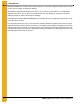
1. Introduction READ THIS MANUAL carefully to learn how to properly use and install equipment. Failure to do so could result in personal injury or equipment damage. INSPECT the shipment immediately upon arrival. The customer is responsible for ensuring that all quantities are correct. The customer should report and note any damage or shortage on the bill of lading to justify their claim to the transport company.
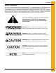
2. Safety Safety Guidelines This manual contains information that is important for you, the owner/operator, to know and understand. This information relates to protecting personal safety and preventing equipment problems. It is the responsibility of the owner/operator to inform anyone operating or working in the area of this equipment of these safety guidelines. To help you recognize this information, we use the symbols that are defined below. Please read the manual and pay attention to these sections.
2. Safety General Safety Statement Our foremost concern is your safety and the safety of others associated with grain handling equipment. This manual is to help you understand safe operating procedures and some problems which may be encountered by the operator and other personnel. As owner and/or operator, you are responsible to know what requirements, hazards and precautions exist and inform all personnel associated with the equipment or in the area. Safety precautions may be required from the personnel.
2. Safety Safety Instructions Our foremost concern is your safety and the safety of others associated with this equipment. We want to keep you as a customer. This manual is to help you understand safe operating procedures and some problems which may be encountered by the operator and other personnel. As owner and/or operator, it is your responsibility to know what requirements, hazards and precautions exist, and to inform all personnel associated with the equipment or in the area.
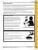
2. Safety Prepare for Emergencies Be prepared if fire starts. Keep a first aid kit and fire extinguisher handy. Keep emergency numbers for doctors, ambulance service, hospital and fire department near your telephone. Keep Emergency Equipment Quickly Accessible Wear Protective Clothing Wear close fitting clothing and safety equipment appropriate to the job. Eye Protection Remove all jewelry. Gloves Long hair should be tied up and back.
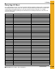
2. Safety Safety Sign-Off Sheet As a requirement of O.S.H.A., it is necessary for the employer to train the employee in the safe operating and safety procedures for this auger. This sign-off sheet is provided for your convenience and personal record keeping. All unqualified persons are to stay out of the work area at all times. It is strongly recommended that another qualified person who knows the shut down procedure be in the area in the event of an emergency.
2. Safety Proper Storage Grain Bin/Silo Materials Prior to Construction Wet storage stain (rust) will develop when closely packed bundles of galvanized material, such as sidewall and roof sheets, have moisture present. Inspect roof and sidewall bundles on arrival for any moisture. If moisture is present, it must not be allowed to remain between the sheets. Separate the sheets or panels immediately and wipe them down. Spray with a light oil or diesel fuel.
3. Safety Decals The manufacturer does not warrant any roof damage caused by excessive vacuum or internal pressure from fans or other air moving systems. Adequate ventilation and/or “makeup air” devices should be provided for all powered air handling systems. The manufacturer does not recommend the use of downward flow systems (suction). Severe roof damage can result from any blockage of air passages. Running fans during high humidity/cold weather conditions can cause air exhaust or intake ports to freeze.
3. Safety Decals ATTENTION: The decal shown below should be present on the outside of the door cover of the 2 ring, 24" porthole door cover and the roof manway cover. If a decal has been damaged or is missing in any of these locations, contact the manufacturer for a free replacement decal. GSI Decals 1004 E. Illinois St. Assumption, IL. 62510 Phone: 217-226-4421 Rotating flighting will kill or dismember. Flowing material will trap and suffocate. Crusted material will collapse and suffocate.
3. Safety Decals ATTENTION: The decal shown below should be present on the outside of the door cover of the 2 ring, 24" porthole door cover and the roof manway cover. If a decal has been damaged or is missing in any of these locations, contact the manufacturer for a free replacement decal. GSI Decals 1004 E. Illinois St. Assumption, IL. 62510 Phone: 217-226-4421 WARNIN DON’T DO UNLOADING INSTRUCTIONS: 1. Use CENTER FLOOR OUTLET ONLY until NO grain remains above this outlet. 2.
4. Assembly Instructions Written Instructions for Installation of a VTDL-72-8X9D - VTDL-78-8X9D Large Vehicle Traffic Door in 72'-78' Diameter, Externally Stiffened Tanks Prior to door installation, tank should be fully erected and anchored. The VTDL door is to be installed in the bottom 4 rings of the tank. Adequate provisions should be made for door installation. A list of necessary tools and equipment is attached. Also some field fabrication and welding will be necessary. 1.
4. Assembly Instructions 8. The center column weldments (VTDL-0383) will be installed within the doorframe. The bottom of the center column weldment will rest between the column outer cover strip on the threshold weldment. The top of the center column weldment will bolt to the header beam weldment with 1" x 3-1/2" bolts. See details B and C on Page 22. Use VTDL-0338 shim plates between center column and header beam and threshold weldment.
4. Assembly Instructions 15. Assemble outer cover as shown on Page 27. Apply strip of caulk behind column and header angles before attaching them to column and header beam clips. Attach center post and center door latch (VTDL-0293) to header angle and threshold weldment. Apply caulking to the top and bottom of center post. Assemble door outer cover, reinforcement channels, hinges, latch brackets and door handles as shown on Page 27. 3/8" x 1" Bin bolts will be used for all connections.
5.
MANWAY DOOR PANEL ASSEMBLY REFER SEE PAGES PAGE 23-24 OUTER COVER ASSEMBLY REFER PAGE 27 DOOR PANEL ASSEMBLY REFER PAGES 23-24 5.
5.
THE HEADER BEAM MUST SLIDE ONTO THE COLUMNS FROM THE INSIDE OF THE TANK. THE SEAL STRIP ATOP OF THE HEADER WILL BOLT TO THE FIFTH RING FROM THE INSIDE OF THE TANK. ATTACH THE HEADER TO THE COLUMNS WITH 1" x 3-1/2" GRADE 8 BOLTS, NUTS AND WASHERS. REFER PAGE 21 FOR HEADER TO COLUMN CONNECTION DETAILS. REQUIRED FIELD WELDING SHOULD BE DONE AFTER DOOR IS COMPLETELY INSTALLED. FIELD WELD SIDEWALL PLATES AND DOOR ATTACHMENT PLATES AS SHOWN. REFER PAGE 26 FOR COMPLETE WELD DETAILS. (VIEWED FROM INSIDE OF TANK).
NOTE: INSTALL HEADER BEAM ONTO COLUMNS AS SHOWN ON PAGE 20. USE 1" x 3-1/2" GRADE 8 BOLTS WITH WASHER ON EACH SIDE. INSERT BOLT FROM THE COLUMN SIDE AND TIGHTEN. ACCESS COVER PLATES (VTDL-0246) WILL BE WELDED ONTO THE INSIDE AND OUTSIDE OF THE COLUMNS AT THE ACCESS OPENING AFTER THE DOOR IS INSTALLED. BE SURE THAT THE EDGE OF THE THRESHOLD PLATE IS ALIGNED WITH THE EDGE OF THE COLUMNS. FIELD WELD THRESHOLD PLATES, SIDEWALL PLATES, AND DOOR PANEL PLATES AFTER DOOR IS COMPLETELY INSTALLED. 5.
5.
DOOR PANELS SHOULD BE ASSEMBLED AS SHOWN. ATTACH THE DOOR PANELS TO THE COLUMNS, HEADER, AND THRESHOLD WITH 1" x 2-1/2" GRADE 8 BOLTS WITH WASHERS ON EACH SIDE. BOLT HEAD SHOULD BE ON THE OUTSIDE OF THE CONNECTION. USE 1" x 3-1/2" GRADE 8 BOLTS AT HINGE LOCATIONS. USE FOAM SEAL STRIP ON BACK SIDE OF DOOR PANELS. APPLY CAULKING BETWEEN ALL DOOR PANEL SPLICES. ATTACH HINGE WELDMENTS TO DOOR PANELS WITH 3/8" x 1-1/2" BIN BOLTS. BOLT HEAD WITH SEALING WASHER SHOULD BE ON THE INSIDE FOR THESE CONNECTIONS.
5.
5.
5.
5.
5.
5. Door Assembly VTDL Door Foundation Note VTDL doors will require special foundation requirements and aeration floor systems. The following pages (Pages 30, 31 and 32) contain foundation specifications for the installation of VTDL doors in 72' through 78' diameter externally stiffened tanks. These specifications are based on the Grain Systems Concrete Manual PNEG-318. All foundation specifications shall be construed as recommendations only.
R417-3/4 STD INNER WALL RADIUS 5.
3'-0" 5.
R40' 7" OUTER WALL RADIUS 5.
6. Warranty The GSI Group Limited Warranty The GSI Group, Inc. (“GSI”) warrants products which it manufactures to be free of defects in materials and workmanship under normal usage and conditions for a period of 12 months after sale to the original end-user or if a foreign sale, 14 months from arrival at port of discharge, whichever is earlier.
This equipment shall be installed in accordance with the current installation codes and applicable regulations which should be carefully followed in all cases. Authorities having jurisdiction should be consulted before installations are made. GSI Group 1004 E. Illinois St. Assumption, IL 62510-0020 Phone: 1-217-226-4421 Fax: 1-217-226-4420 www.gsiag.