Sidewall Bin Stair Assembly Assembly Manual PNEG-1112 Date: 03-12-10 PNEG-1112
PNEG-1112 Sidewall Bin Stair Assembly
Table of Contents Contents Chapter 1 Safety .................................................................................................................................................. 4 Safety Guidelines ............................................................................................................................... 4 General Safety Statement .................................................................................................................. 5 Safety Instructions ........
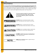
1. Safety Safety Guidelines This manual contains information that is important for you, the owner/operator, to know and understand. This information relates to protecting personal safety and preventing equipment problems. It is the responsibility of the owner/operator to inform anyone operating or working in the area of this equipment of these safety guidelines. To help you recognize this information, we use the symbols that are defined below. Please read the manual and pay attention to these sections.
1. Safety General Safety Statement Our foremost concern is your safety and the safety of others associated with grain handling equipment. This manual is to help you understand safe operating procedures and some problems which may be encountered by the operator and other personnel. As owner and/or operator, you are responsible to know what requirements, hazards and precautions exist and inform all personnel associated with the equipment or in the area. Safety precautions may be required from the personnel.
1. Safety Safety Instructions Our foremost concern is your safety and the safety of others associated with this equipment. We want to keep you as a customer. This manual is to help you understand safe operating procedures and some problems which may be encountered by the operator and other personnel. As owner and/or operator, it is your responsibility to know what requirements, hazards and precautions exist, and to inform all personnel associated with the equipment or in the area.
1. Safety Prepare for Emergencies Be prepared if fire starts. Keep a first aid kit and fire extinguisher handy. Keep emergency numbers for doctors, ambulance service, hospital and fire department near your telephone. Keep Emergency Equipment Quickly Accessible Wear Protective Clothing Wear close fitting clothing and safety equipment appropriate to the job. Eye Protection Remove all jewelry. Long hair should be tied up and back.
2. Installation Read and follow these directions carefully before an attempt is made at installation. The GSI Group is not responsible for damage or accidents caused by improper installation or installation procedures. Our stairs are designed to support the weight of one (1) person, and the weight that they can carry. NOTE: The sidewall bin stair assembly can be installed ascending or descending, clockwise or counterclockwise, when looking at a top down view of the bin.
2. Installation 3. Consult Figure 2B on Page 10 through Figure 2G on Page 15 for the layout of the attachment points, and where you will have to field drill. 4. Line up the correct hole in the platform wall bracket with the first horizontal seam bolt row. The correct hole is indicated in the detail view of the corresponding layout figure. Knee braces should be installed at the same time as the platform wall brackets. 5.
2.
2.
2.
2.
2.
2.
2. Installation Platform Assembly and Installation Assembling the Platform at Ground Level 1. Attach the 51-1/2'' left platform post to the platform using two (2) 5/16'' x 3/4'' bin bolts and serrated flange nuts. The head of the bin bolts should be on the inside of the platform. The cut edge of the platform post should be located on the side of where the platform will attach to the platform wall bracket. See Figure 2H and for an alternate view, see Figure 2I.
2. Installation 2. Attach the corner platform post to the closest corner (opposite the platform wall bracket side of the platform), using two (2) 5/16'' x 3/4'' bin bolts and serrated flange nuts. The head of the bin bolts should be on the inside of the platform. Figure 2J 3. Next, attach the 51-1/2" right platform post in between the platform and the outside siderail extension using three (3) 5/16" x 3/4'' bin bolts and serrated flange nuts.
2. Installation Figure 2L 4. Install one (1) 5/16'' x 3/4'' bin bolt and serrated flange nut to join the outside siderail extension and the 51-1/2'' right platform post.
2. Installation 5. Attach the 9-1/2" sidewall post in between the platform and the inside siderail extension on the final corner of the platform using three (3) 5/16'' x 3/4'' bin bolts and serrated flange nuts. The post should point down from the top of the platform. The head of the bin bolts should be on the inside of the platform. Figure 2N 6.
2. Installation 7. Bolt the two (2) 39'' sidewall stair handrails to the outside of the 51-1/2'' right platform post and the outside of the corner post using four (4) 5/16'' x 1-1/2'' carriage bolts and serrated flange nuts. Make sure that the handrails are fully seated on the posts. Figure 2P Attach the Platform Assembly to the Platform Wall Brackets and Knee Braces 1.
2.
2. Installation Assemble Steps to Siderails Stair Section Assembly The 2 step, 3 step, and 4 step stair sections are all assembled in the same fashion. The following instructions are for assembling a 3 step stair section. The inside stair siderail is different from the outside stair siderail in the same way as the inside and outside siderail extensions. The outside stair siderail has three (3) slots at its ends, while the inside stair siderail has two (2) slots.
2. Installation 2. Repeat Step 1 on Page 22 for the quantity of steps in the package. Figure 2T 3. Loosely attach the outside stair siderail to the 9'' x 20'' steps using two (2) 5/16'' x 3/4'' bin bolts and serrated flange nuts for each step. The heads of the bin bolts should be on the outside of the outside stair siderail and not to the inside of the step. Figure 2U NOTE: 4 Step sections have slots for the top and bottom step attachment to the outside stair rail.
2. Installation 4. Loosely bolt the handrail baluster to the outside stair siderail using one (1) 5/16" x 3/4" bin bolt and serrated flange nut. The bin bolt and serrated flange nut should be preliminarily installed to the inside end of the rear slot for bins greater than 30' in diameter, and to the hole outside of the slots for bins less than or equal to 30' in diameter. Figure 2V Figure 2W 5. The loosely assembled stair section is now ready to be installed on the bin.
2.
2. Installation Inside Stair Siderail Attachment Lift the assembled stair section close to the installed platform assembly. 1. Sandwich the inside stair siderail from the assembled stair section between the inside of the inside siderail extension, and the outside of the 9-1/2'' sidewall post.
2. Installation 2. Insert two (2) 5/16'' x 3/4" bin bolts into the two (2) mating slots on the inside of the inside stair siderail, and one (1) 5/16'' x 3/4'' bin bolt to the bottom hole on the 9-1/2'' sidewall post. Loosely join the bin bolts to two (2) serrated flange nuts on the outside of the inside siderail extension, and one (1) serrated flange nut on the inside of the platform wall bracket.
2. Installation 3. Insert two (2) 5/16'' x 3/4'' bin bolts into the two (2) mating slots on the inside of the outside siderail extension. Loosely join the bin bolts to two (2) serrated flange nuts on the outside of the outside stair siderail. These bin bolts and serrated flange nuts will be adjusted and tightened after the assembled stair section is in place. Figure 2AC Inside Stair Siderail Attachment to Wall Bracket 1.
2. Installation Attach Handrail Baluster to Knee Brace 1. Bring the bottom of the handrail baluster to the top of the nearest installed knee brace. 2. Loosely attach the handrail baluster to the knee brace using two (2) 5/16'' x 3/4'' bin bolts and serrated flange nuts. The head of the one (1) bin bolt should be on the handrail baluster and the head of the other bin bolt should be on the knee brace. 3.
2. Installation Attachment of Consecutive Stair Sections NOTE: Depending on the size of the bin, and the bent edges of the stair siderails, the inside stair siderails can overlap the next inside stair siderail in both directions. (Figure 2AG and Figure 2AH on Page 31.) The outside stair siderails have the same possibilities. It is important to assemble the stair sections consistently, therefore keep the overlap the same for each consecutive section.
2.
2. Installation Attaching the Inside Siderail Bring the next assembled stair section to the previously installed stair section. 1. Place the outside surface of the inside stair siderail to the inside of the already installed inside stair siderail. 2.
2. Installation Attaching the Outside Siderail 1. Place the inside surface of the outside stair siderail to the outside surface of the already installed outside stair siderail. 2. Using Figure 2AK and Figure 2AM, loosely bolt the two (2) outside stair siderails together with two (2) 5/16'' x 3/4'' bin bolts and serrated flange nuts, and the outside stair siderail to the handrail baluster with one (1) 5/16'' x 3/4'' bin bolt and serrated flange nut. Note the four (4) total attachment points on the figures.
2. Installation Figure 2AM 4. Figure 2AN shows a detail of the overlapping outside rails of a 4 step section. The figure is to be used for 21' to 36' diameter bins. The chart associated with the figure gives an approximate relation between the two (2) outside rails. This chart is a guideline only. Overlap distances may vary in order to keep the stairs level. Use a level to ensure the stairs are level in all directions.
2. Installation Installation of Bottom Brace and Bracket Bottom Brace Bracket 1. For the last stair section, attach the wall bracket to the bin wall, using the bottom hole in the wall bracket, with one (1) 5/16'' x 1-1/4'' bin bolt and serrated flange nut. 2. The bottom brace bracket installs to the outside stair siderail and the handrail baluster on one end, and the wall bracket and inside stair siderail on the other end. 3.
2. Installation 4. Attach the bottom brace bracket to the outside stair siderail and the handrail baluster using two (2) 5/16'' x 3/4'' bin bolts and serrated flange nuts. Figure 2AP Field cut the handrail baluster below the bottom brace bracket so that it does not interfere with the bin pad or ground.
2. Installation Lower Support of the Stairs 1. In some cases the foundation is not as wide as the outside of the stair section. In this case, the outside of the stair section needs to be supported to keep the stairs level. This should be done by field fabrication of an angle back to the concrete foundation or supporting the outside rail with blocks or a concrete pad. Use a level to check the stairs in all directions and shim the outside rail when necessary. Bottom Knee Brace 1.
2. Installation Handrail Installation After all the stair sections have been assembled and installed, the upper and lower handrails can be installed. The handrails can be installed top down, or bottom up. The handrails have a smaller diameter at their upper ends, and have a pre-drilled hole at the lower end to aid installation. NOTE: The lengths of handrails that are provided correspond to the differing stair section lengths. Assemble the correct handrails to the appropriate stair sections.
2. Installation NOTE: The handrails are not shipped pre-curved. As the lower and upper handrails are installed, they must be curved/bent to match the curve of the bin, and in order to attach to the handrail balusters at the appropriate attachment points. 2. With the next appropriate length handrail, overlap the to-be-installed handrail to the previously installed handrail. The two (2) handrails should overlap by at least 2''. Figure 2AV 3.
2. Installation 5. Where the assembled lower handrail meets the 51-1/2'' right platform post, use one (1) 1/4'' x 1'' self drilling screw to attach it to the outside surface of the post. The head of the screw should be on the inside surface of the 51-1/2'' right platform post. Figure 2AX Upper Handrail Installation 1.
2. Installation NOTE: In the same way that the lower handrails had to be curved/bent to match the curve of the bin, the upper handrails have to be adjusted to match. 2. With the next appropriate length handrail, overlap the to-be-installed handrail to the previously installed handrail. The two (2) handrails should overlap by at least 2''. 3.
3.
3.
3.
3.
3.
3.
3.
3.
NOTES 50 PNEG-1112 Sidewall Bin Stair Assembly
4. Warranty GSI Group, LLC Limited Warranty The GSI Group, LLC (“GSI”) warrants products which it manufactures to be free of defects in materials and workmanship under normal usage and conditions for a period of 12 months after sale to the original end-user or if a foreign sale, 14 months from arrival at port of discharge, whichever is earlier.
This equipment shall be installed in accordance with the current installation codes and applicable regulations which should be carefully followed in all cases. Authorities having jurisdiction should be consulted before installations are made. GSI Group 1004 E. Illinois St. Assumption, IL 62510-0020 Phone: 1-217-226-4421 Fax: 1-217-226-4420 www.gsiag.