54' Diameter Bins Cor-Lok and Cut-Lok Flooring and Grandstand Layout Installation Manual PNEG-1567 Date: 09-27-12 PNEG-1567
PNEG-1567 54' Cor-Lok and Cut-Lok Flooring
Table of Contents Contents Chapter 1 Safety .....................................................................................................................................................4 Safety Guidelines .................................................................................................................................. 4 Safety Instructions .................................................................................................................................
1. Safety Safety Guidelines This manual contains information that is important for you, the owner/operator, to know and understand. This information relates to protecting personal safety and preventing equipment problems. It is the responsibility of the owner/operator to inform anyone operating or working in the area of this equipment of these safety guidelines. To help you recognize this information, we use the symbols that are defined below. Please read the manual and pay attention to these sections.
1. Safety Safety Instructions Our foremost concern is your safety and the safety of others associated with this equipment. We want to keep you as a customer. This manual is to help you understand safe operating procedures and some problems that may be encountered by the operator and other personnel. As owner and/or operator, it is your responsibility to know what requirements, hazards, and precautions exist, and to inform all personnel associated with the equipment or in the area.
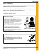
1. Safety Prepare for Emergencies Be prepared if fire starts. Keep a first aid kit and fire extinguisher handy. Keep emergency numbers for doctors, ambulance service, hospital, and fire department near your telephone. Keep Emergency Equipment Quickly Accessible Wear Protective Clothing Wear close-fitting clothing and safety equipment appropriate to the job. Eye Protection Remove all jewelry. Tie long hair up and back. Gloves Wear safety glasses at all times to protect eyes from debris.
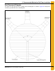
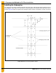
2. Recommended Method for Full Floor Installation Fan Placement Diagram For uniform air flow, place the fans in relation to the unloading tube as shown in Figure 2A. Floor planks should be perpendicular to the unloading tube.
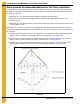
2. Recommended Method for Full Floor Installation Grain Systems Recommended Method for Full Floor Installation Using the GSI recommended method for full floor installation should save construction time and eliminate the problem of improper installation which could invalidate your warranty. Note the following dimensions as shown in Figure 2B. • Dimension “A” is the leg-to-leg spacing along the centerline of a given plank.
2. Recommended Method for Full Floor Installation IMPORTANT: First piece of flooring must start at the proper distance from centerline of bin. Refer to floor layout on Page 15. First piece may need to be trimmed for length to fit at the proper location. Figure 2C 4. When completed there should be a set of parallel lines “B” dimensions apart. 5. Start at bin wall with shortest floor piece. POSITION SUPPORTS FOR THIS PIECE AS SHOWN ON SUPPORT LAYOUT FOR CORRECT BIN DIAMETER AND SUPPORT SPACING.
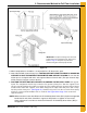
2. Recommended Method for Full Floor Installation Installing the Undersplice The undersplice should be installed underneath the planks at the split after both plank lengths have been butted together. Each splice has to be laid as each row of planks are laid rather than after all have been placed. Figure 2D shows the layout of the undersplice plates and the screw pattern used to secure them.
2. Recommended Method for Full Floor Installation Installation Instructions 1. When a splice is needed, plank length A as described in the floor manual should be installed alongside plank length B. 2. The under-splice should then be installed under the split of plank A and B. The splice should extend 3" under each plank. The splice should be screwed in place as shown in Figure 2D on Page 10. 3. This process will be repeated for all plank locations requiring a splice.
3.
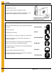
4. Flashing Installation Figure 4A Grain Systems Formed Flashing Installation If a bin sweep auger will be used, overlap flashing so that the sweep will climb up on to the next flashing section when rotating (usually clockwise). (See Figure 4A.) This will prevent the rotating/slipping outer wheel of the sweep from catching on the flashing edges. (All GSI power sweeps and carry-in sweeps manufactured after April 2002 run clockwise.
5. Well Installation Cut Detail CAUTION Support all center wells to concrete.
CAUTION Support all center wells to concrete. 6.
7. Plank Lengths The following plank lengths start at the sidewall and work towards the center of the bin. Refer to grandstand layout pages for floor drawing.
8. 20 Gauge Floor Support Requirements 20 Gauge Grandstand Chart - 2.66" Corrugation Narrow/2.66" Corrugation - 20 Gauge Grandstand Floor Support Chart Rings Dia.
8. 20 Gauge Floor Support Requirements 20 Gauge Grandstand Chart - 4.00" Corrugation Wide/4.00" Corrugation - 20 Gauge Grandstand Floor Support Chart Full Floor Supports Required for Plank Type Flooring 4.00" Corrugation (* Based Upon 13-1/2" or Taller Floor Heights) Rings Dia. 12 15 18 21 24 27 30 33 36 39 42 45 48 54 60 SUPPORT SPACING SUPPORT QUANTITY 72 75 78 90 105 All floor styles OK for bin sizes in upper shaded area.
9. Flashing Support at Stiffeners Stiffener Flashing Support Instructions for Internal Universal Stiffeners 1. Install the floor and support system, cutting the floor to go around the internal stiffeners as required. 2. Break the stiffener flashing support (SS-6984) into its three (3) components. 3. Lay the flashing supports on top of the flooring and weld the flashing supports to the stiffener as close as possible. Fasten the flashing to the wall, flashing support and floor.
10. Air Flow Support Instructions Installation of Air Flow Supports 1. Determine the spacing and quantity of air flow supports required from the chart on Page 22. Make sure that the correct supports have been ordered for use with the proper depth of plank (either 1-1/8" or 1-3/8" deep). 2. Mark location of center of bin. 3. Install discharge auger. 4. Mark spacing lines parallel to discharge auger. 5.
10. Air Flow Support Instructions The following Figure 10A show methods of support placement to achieve the necessary spacing close to discharge augers and sumps.
10. Air Flow Support Instructions * Installation, Spacing and Quantities of Air Flow Supports Under Channel Lock Floors Bin Diameter - Number of Supports Grain Depth at Bin Wall (ft.) Spacing (in.) 18' 18 Ft. Dia. 21 Ft. Dia. 24 Ft. Dia. 27 Ft. Dia. 30 Ft. Dia.
10.
10. Air Flow Support Instructions Installation, Spacing and Quantities of Air Flow Supports Under Channel Lock Floors York and Chief Bins Bin Diameter - Number of Supports Grain Depth at Bin Wall (ft.) Spacing (in.
10. Air Flow Support Instructions Installation, Spacing and Quantities of Air Flow Supports Under Channel Lock Floors Behlen Bins Bin Diameter - Number of Supports 16' 5" 19' 8" 22' 11" 26' 3" Grain Depth at Bin Wall (ft.) Spacing (in.
NOTES 26 PNEG-1567 54' Cor-Lok and Cut-Lok Flooring
11. Warranty GSI Group, LLC Limited Warranty The GSI Group, LLC (“GSI”) warrants products which it manufactures to be free of defects in materials and workmanship under normal usage and conditions for a period of 12 months after sale to the original end-user or if a foreign sale, 14 months from arrival at port of discharge, whichever is earlier.
This equipment shall be installed in accordance with the current installation codes and applicable regulations, which should be carefully followed in all cases. Authorities having jurisdiction should be consulted before installations are made. GSI Group 1004 E. Illinois St. Assumption, IL 62510-0020 Phone: 1-217-226-4421 Fax: 1-217-226-4420 www.gsiag.