
Service Manual User guide
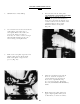

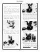

Pick up one of the pressure plates and
note the bronze side. You will notice
that one of the sides has rounded trap
slot milled into it. This side faces the
discharge side of the pump. The dis-
charge side is opposite the isolation
plate. Keeping the plate as level as
possible, slide into place in the bottom
of the body. DO NOT FORCE THE
PLATE! If it binds on the way down,
work it slightly until it slides into place.
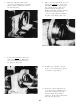
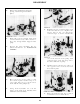
Check the name plate on the body of
the pump for the pump rotation.
REASSEMBLY
In fall the O-ring in place against the
back-up ring so that it seats itself in-
to the groove in the edge of the back-
up ring.
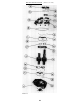
EXAMPLE
Model No.
25660A-D
Denotes Counter clockwise Rotation
Model No.
25660C-D
Denotes Clockwise Rotation
If the pump is of clockwise rotation,
the drive shaft is placed into the bore
nearest you. If the pump is of anti-
clockwise rotation, the drive shaft
goes into the bore away from you.
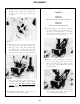
Insert the drive shaft into the proper
bore for this pump. Do not drop into
place, but slide it into place gently
as dropping will damage the bronze
pressure plate.
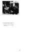
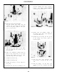
Install the idler gear into the opposite
bore of the pump. The long journal
on the idler gear shouLd be up.
18.
19.
20.
21.
22.
23.
78
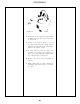
FIGURE 131
FIGURE 133
FIGURE 132
FIGURE 134