
Service Manual User guide
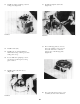
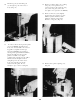

By tightening the vise firmly, but
gently, press the seal into the bore.
Stop the pressure when the seal
touches the shoulder inside the bore.
Replace snap ring, making sure that
it snaps into the groove properly.
Wash the flange thoroughly in sol-
vent. Coat the lips of the seal
with heavy grease.
Bearing Replacement
Mobil-Master Series 20 and 25 pumps are
built with the highest capacity bearings
available. However, if the pump is run
on a system with contaminant present in
the oil, or under certain other con-
ditions, bearing failure may be exper-
ienced. In the event of bearing failure
the bearings may be replaced if the
gears have not cut a track in the
housing deeper than .015 inches.
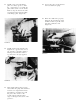
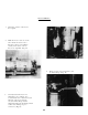
To remove the old bearings, disassemble
the pump and place the body in a vise.
Clamp on the side of the body using
cardboard to prevent marring by the
vise jaws.
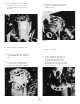
Using the small keyhole type hack saw,
cut through the bearing opposite the
oil groove. Be sure the saw cuts com-
pletely through the bearing shell,
but cuts as little as possible into
the aluminum bore.
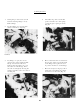
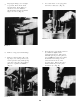
After the cut is made, grip the bearing
with vise-grip pliers and remove it with
a twisting motion. Flange bearings can
be removed in the same manner. Take
care not to damage the bores. After the
old bearings have been removed, wash all
of the parts thoroughly in solvent.
Press in the new body bearings. They
should protrude above the surface
.220/.230 inch. Locate the split in the
flange bearing at the same place the oil
groove in the bronze bearings was
located. The flange bearings, when
replaced, must protrude .220/.230 inch
above the surface.
Install the remaining parts of the
repair kit and replace on the machine.
No break-in is necessary and the unit
is ready to operate at full capacity.
Inspection of Parts
Visually inspect all parts. There
will be a gear track on the inside
of the pump body. Measure the
depth of this gear track. The nomi-
nal depth of this cut is .008"
(0,203 mm) and should not exceed .015"
(0,381 mm). If the track is less
than .015, the body is all right for
assembly provided it is not cracked
or damaged otherwise.
Examine the pressure plates. They
should not show excessive wear on
the bronze side. If deep curved
wear marks are visible, reject them.
Examine the gears. If excessive
wear is visible on the journals,
sides or face of the gears, or at
the point where it rotates in the
seal, reject them.
If any of the internal parts show
excessive wear, replace all the parts
For further information on inspec-
tion of parts, see PUMP TROUBLE-
SHOOTING GUIDE, or DIAGNOSING TYRONE
GEAR PUMP FAILURES.
7.
8.
9.
1.
2.
3.
4.
5.
54