
Service Manual User guide
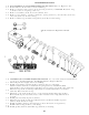

Place thrust washers (3B) inside carrier (3A) with greased side against carrier
(3A) and the tang should be in cut away section of carrier (3A). Thrust washers
(3B) are flat against the surface on both sides of carrier (3A).
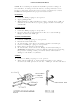
Apply petroleum jelly or grease to bore of one cluster gear (3F). Place two sets
of needle roller bearings (3C) into cluster gear (3F) bore with spacer (3D)
between them. (See Figure).
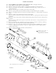
Place cluster gear (3F) into carrier (3A) and between the two thrust washers
(3B). (Be sure that large side of cluster gear (3F) is on same side as pin hole
thru carrier (3A) wall).
Place planet shaft (3E) horizontally thru carrier (3A) wall, thrust washer (3B),
needle rollers bearings (3C), thrust washer (3B) on opposite side, and carrier
(3A) wall. NOTE: The hole in planet shaft (3E) must line-up with pin hole in
carrier (3A) wall. The chamfered side of planet shaft (3F) hole should line-
up with carrier (3A) wall pin hole.
Place roll pin (3G) in vertical hole in carrier (3A) wall and drive into hole
until flush with surface of carrier (3A). (This will keep planet shaft (3E)
from turning).
Repeat these steps for remaining two cluster gears (3F) to complete carrier
sub-assembly.
ASSEMBLY OF
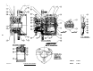
COVER SUB-ASSEMBLY (SEE FIGURE FOR COVER SUB-ASSEMBLY)
Place “O” ring (6F) into cover cap (6B).
Place “O” ring (6G) over cover cap (6B).
Screw pipe plug (6H) into cover (6A).
Put cover cap (6B) into cover (6A) with clearance hole around the pipe plug
(6H).
Place disconnect cap (6D) over the cover cap (6B) again with the clearance cover
the pipe plug (6H).
Assemble (6D) with (four) bolts (6C) into the cover (6A). Two bolts hold cover
cap (6B) and two bolts hold disconnect cap (6D).
Push disconnect rod (6E) into cover cap (6B).
26
3.
4.
5.
6.
7.
8.
1.
2.
3.
4.
5.
6.
7.