
Service Manual User guide
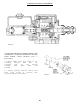

Secure cover sub-assembly (6) and ring gear (4) in place with bolts. Use four
shoulder bolts (18) for counterbored holes in hub of hub-spindle sub-assembly
(1) and use bolts (17) for remaining holes. Tighten bolts to 47 ft. lbs.
maximum.
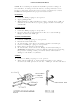
Place coupling (19) into spindle of hub-spindle sub-assembly (1) and meshing
with input shaft (11). On W3C be sure retaining ring (20) is in internal groove
of coupling (19) and retaining ring (21) is located in external groove of
coupling (19).
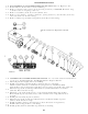
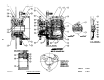
ASSEMBLY PROCEDURE OF
HUB-SPINDLE SUB-ASSEMBLY
Press bearing cups (races) (1C) and (1C) and (1E) into hub (1G).
Set hub (1G) on large end. (Studs and disc are optional)
If required, press studs (1N) into hub (1G) flange.
If required, mount disc (1M) into hub (1G) rigs, and
secure in place with lockwasher (1L) and bolts (1K).
Place bearing cone (1D) into bearing cup (race) (1C).
Preys seal (1B) into hub (1G).
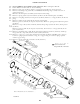
Place spindle (1A) into bearing cone (1D). This is a loose fit and should not
be pressed.
Invert the partial assembly of hub-spindle (1A), (1B), (1C), (1D), (1E), and
(1G). Do not let spindle (1A) slip from hub (1G). Place spindle (1A) down.
Slide bearing cone (1F) onto the spindle (1A) against bearing cup (1E). This
is NOT a press fit.
Place spacer (1H) on spindle (1A).
Place retaining ring (1I) on spindle (1A) groove. Be sure ring is completely
in the groove.
Screw pipe plug (1J) into hub (1G) outside diameter.
The above step completes the sub-spindle sub-assembly (1) and the hub (1G)
should turn freely with respect to the spindle (1A). The seal will cause a
small amount of drag.
ASSEMBLY PROCEDURE FOR CARRIER SUB-ASSEMBLY
Set carrier (3A) on edge so that six small holes and two center holes are in
a horizontal plane.
Lay two thrust washer (3B) on a flat surface with the tang facing up. Apply
petroleum jelly or grease to this surface of both thrust washer (3B).
23.
24.
1.
2.
3.
4.
5.
6.
7.
8.
9.
10.
11.
1.
2.
2A.
2B.
25