
Service Manual User guide
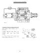

PLANETARY HUBS
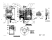
ASSEMBLY PROCEDURE FOR MAJOR ASSEMBLY
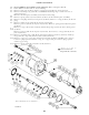
Start with hub-spindle sub-assembly (1) with large open end up.
Assemble internal gear (2) onto the spindle of hub-spindle sub-assembly (1).
Place thrust washer (15) onto the spindle pilot of hub-spindle sub-assembly (1).
Place thrust bearing (16) onto spindle pilot of hub-spindle sub-assembly (1).
Place thrust washer (15) onto spindle pilot of hub-spindle sub-assembly (1).
Drop spacer washer (7) into spindle of hub-spindle sub-assembly (1).
Place spring (8) into spindle of hub-spindle sub-assembly (1).
Place spacer washer (7) into spindle of hub-spindle sub-assembly (1).
Secure retaining ring (9) into groove in spindle of hub-spindle sub-assembly (1).
Secure retaining ring (10) in groove on input shaft (11).
Place long splined end of input shaft (11) into spindle of hub-spindle hub-
assembly (1).
Slide thrust spacer (12) onto input shaft (11).
Put “O” ring (5) in hub counterbore of hub-spindle.
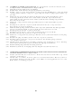
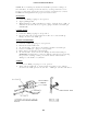
Place carrier sub-assembly (3) on a flat surface with large gears up. Find
marked (punch marked) teeth on the large gears. Rotate until the marks are in
a straight-up position. (See Figure).
Place ring gear (4) over large gears of carrier sub-assembly (3).
Holding ring gear (4) in mesh with large gears, pick-up carrier sub-assembly (3)
until marked hold is located over one of the counterbored holes in hub of hub-
spindle sub-assembly (1). Carrier sub-assembly (3) must rotate freely.
Put input gear (13) over input shaft (11) and meshing with large gears of carrier
sub-assembly. Be sure that input gear (13) relief is as shown. (See Figure).
Put “O” ring (5) into cover counterbore of cover sub-assembly (6). Hold “O”
ring in place with petroleum jelly or grease.
Place thrust washer (15) into carrier counterbore of carrier sub-assembly (3).
Place thrust bearing (16) into carrier counterbore of carrier sub-assembly (3).
Place thrust washer (15) into carrier counterbore of carrier sub-assembly (3).
Place cover sub-assembly (6) onto ring gear (4) with oil check plug in cover
sub-assembly (6) located 90 from oil fill plug in hub-assembly sub-assembly
(1).
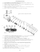
1.
2.
3.
4.
5.
6.
7.
8.
9.
1 0 .
1 1 .
12.
13.
14.
15.
16.
17.
18.
19.
20.
21.
22.
24