
Service Manual User guide
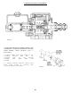

POWER ASSIST SECTION
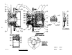
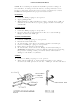
DISASSEMBLY OF POWER ASSIST SECTION. Refer to Figures 20 & 23.
Drain fluid from unit before disassembling.
Remove push rod (item 18) and boot (item 19) from Power Assist Section.
Remove retaining ring (item 20). CAUTION: Retaining ring is under tension of
spring (item 33).
Remove internal parts assembly (item 45) from housing.
Remove spring (item 33) and retainer (item 32) from internal parts assembly.
Remove end plug (item 21) from piston (item 25). Remove o’ring (item 22) from end
plug.
Remove retainer ring (item 34) from piston (item 25).
Remove piston (item 31) from piston (item 25). Remove spring (item 30) from piston
(item 25).
Remove v-cup seals (items 24 & 26) and back-up rings (items 23 & 27) from piston
(item 25)
Remove piston (item 29) from piston (item 25), then remove o’ring (item 28) from
piston (item 29).
Remove retaining ring (item 40) from housing. Remove washer (item 39), back-up
ring (item 38), cup seal (item 37) and washer (item 36).
Remove o’ring or copper ring (item 43) from plug (item 44). NOTE: if an o’ring is
found on plug replace with an o’ring, if a copper ring is found on plug replace
with a copper ring.
Remove spring (item 42) and valve stem (item 41).
4 . 0
4 . 1
4 . 2
4 . 3
4 . 4
4 . 5
4 . 6
4 . 7
4 . 8
4 . 9
4 . 10
4 . 11
4 . 12
4 . 13
Power Assist Section continued . . .
22
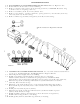
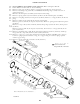
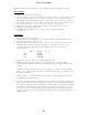
Items included in
Repair Kit No. 202-596
FIGURE 23