
Service Manual User guide
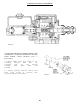
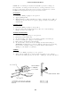

CYLINDER RESERVOIR SECTION
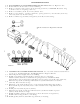
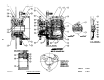
DISASSEMBLY OF CYLINDER RESERVOIR SECTION. Refer to Figures 1 & 3.
Drain fluid from unit before disassembling.
Remove retainer ring (item 1) from housing (item 14). CAUTION: Retainer ring
is under tension of spring (item 11).
Remove assembly (item 17) from cylinder bore.
Remove cup (item 9), retainer (item 10), spring (item 11), check valve (item 12),
and seat (item 13) from housing.
Remove filler cap (item l6) and gasket (item l5) from housing.
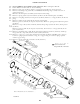
ASSEMBLY OF CYLINDER RESERVOIR SECTION. Use only brake fluid in Cylinder Reser-
voir Section. Use Repair Kit No. 02-400-058. Refer to Figures 20 & 22.
Clean all parts thoroughly before assembling.
Install seat (item l3) and check valve (item 12) in bore of housing.
Attach retainer (item 10) to small end of spring (item 11). Install assembly
items 10 & 11) into housing bore with large end of spring over check valve (item 12).
Lubricate cup (item 9) with type fluid used in system and install over retainer
(item 10). Note direction of cup.
Lubricate v-cup seals (items 2 & 5), o-ring (item 4) and back-up ring (item 3).
Then install on piston (item 6). Note order of washer and o-ring and direction
of seals.
Install piston (item 6) in piston (item 8).
Lubricate cup (item 7) with type fluid used in system and install on piston
(item 8). Note direction of cup.
Install assembly (item 17) in housing bore. Note direction of cup (item 7).
Install retainer ring (item 11) on housing.
Install gasket (item 15) and filler cap (item 16) on housing.
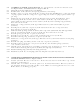
Items included in Repair Kit 202-595
21
2 . 0
2 . 1
2 . 2
2 . 3
2 . 4
2 . 5
3 . 0
3 . 1
3 . 3
3 . 4
3 . 5
3 . 6
3 . 7
3 . 8
3 . 9
3 . 10
FIGURE 22