
Service Manual User guide
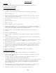
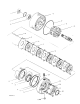

PARKING BRAKE
FUNCTION
The Parking Brake is spring loaded to apply the brake. Hydraulic pressure is used
to release or hold “off” the brake.
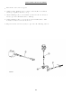
DISSASSEMBLY PROCEDURE
Loosen 2 bolts (22) alternately.
Separate power plate (18) assembly from the remainder of the brake.
Remove O-ring (5).
Remove rotating disc (10) from splined shaft (7), remove springs (12) and
stationary disc (11) from pins (8).
Repeat until all rotating discs (10), stationary disc (ll) and springs (12)
are removed.
Remove primary disc (9).
Remove pins (8).
Remove springs (6) from counter bores.
Further disassembly of the seal (1), snap ring (2), bearing (3), and shaft
(7), from the housing (4) is not recommended, and should not be attempted
unless necessary for the replacement of specific parts.
Remove seal (1). The seal will be damaged during removal and must be
replaced.
Remove retaining ring (2).
Remove shaft (7) and bearing (3) by lightly tapping the shaft with a plastic
mallet.
Remove shaft from bearing by supporting the inner race of the bearing and
pressing the shaft out of the race.
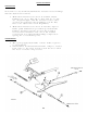
Remove the piston (13) from the power plate (18) by introducing low pressure -.
air - 15 psi - into the hydraulic inlet. Make sure piston is directed
away from the operator.
Remove O-rings (15,17) and teflon back-up rings (14,16) from the O. D. and
I. D. ring grooves. Removal of the teflon back-up rings (14,16) may cause
damage to the teflon rings and should not be attempted unless necessary.
Remove snap ring (20).
Remove bearing (21) by tapping lightly with a plastic mallet.
ASSEMBLY PROCEDURE
Use the reverse of dissassembly with the following note and additions:
Worn O-rings and damaged or worn teflon back-up rings must be replaced
prior to reassembly.
Cylinder of the power plate, piston and O-rings must be clean prior to
assembly, and pre-lubed with system hydraulic fluid.
Assemble piston (13) into power plate (18) using a shop press, being careful
not to damage the O-rings or the teflon back-up rings. Visually align the
center of the cut-outs in the piston (13) with the torque pin (8) holes in
the power plate (18).
Rotating discs must be clean and dry. There should be no pressure of oil
on any lining material or mating surfaces of the stationary discs.
Alternately tighten bolts (22) and torque them to 75-85 lb. ft.
1.
2.
3.
4.
5.
6.
7.
8.
9.
10.
11.
12.
13.
14.
15.
16.
17.
1.
2.
3.
4.
5.
18