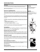
G6-42P MATERIAL HANDLER OWNER/OPERATOR MANUAL m a t e r i a l h a n d l e r COVERING OPERATION & PERIODIC MAINTENANCE IMPORTANT! Read and understand this Manual and the Gradall Material Handler Safety Manual before starting, operating or performing maintenance procedures on this machine. KEEP OPERATOR AND SAFETY MANUALS IN CAB A ® Company Form No. #20027 COVERS MATERIAL HANDLER MODEL G6-42P STARTING SERIAL NUMBERS 0189001 THRU 0189345, & 0160000230 THRU 0160004017 ® Part No.
1234567890123456789012345678901212345678901234567890123456789012123456 1234567890123456789012345678901212345678901234567890123456789012123456 1234567890123456789012345678901212345678901234567890123456789012123456 1234567890123456789012345678901212345678901234567890123456789012123456 1234567890123456789012345678901212345678901234567890123456789012123456 1234567890123456789012345678901212345678901234567890123456789012123456 1234567890123456789012345678901212345678901234567890123456789012123456 123456789012345
REVISIONS This page is provided so you may determine that this Manual is complete and current with respect to Gradall Engineering Specifications. Page Date Revision 11.0 9/24/01 Revised section on checking and adjusting boom. 16.0 7/22/02 Added an additional lubrication notice. Cover 5/23/03 Revised All Intro Revised Operator Qualification section. TOC Added page 20.2 to Table Of Contents. 2.0 Replaced 9140-3525 Decal with 9150-3102 Decal. 2.
TABLE OF CONTENTS IMPORTANT SAFETY NOTICE ..................................................... TABLE OF CONTENTS INTRODUCTION General Operator Qualifications Orientation Related Manuals & Decals Serial Number Location NOMENCLATURE SAFETY ................................................................................. DECALS ................................................................................. Decals Inside Cab Decals Outside Cab OPERATORS CAB ...................................................
INTRODUCTION General This Manual provides important information regarding safe operating procedures and maintenance requirements for GRADALL G6-42P Material Handlers. If you have any questions regarding the material handler, contact your GRADALL Material Handler Distributor. Operator Qualifications Operators of the material handler must be in good physical and mental condition, have normal reflexes and reaction time, good vision and depth perception and normal hearing.
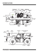
NOMENCLATURE MIRROR ENGINE BATTERY HYDRAULIC FILTERS AIR CLEANER HYDROSTATIC TRANSMISSION CONTROL VALVES IMPLEMENT PUMP - ENGINE & VALVE COMPARTMENT + STEERING CYLINDER SWAY CYLINDER TIE-DOWN LUGS TIE DOWN LUGS FRONT DRIVE AXLE STEERING CYLINDER OPERATORS CAB BOOM SECTION 3 BOOM SECTION 2 BOOM HEAD BOOM SECTION 1 HYDRAULIC RESERVOIR OPERATORS CAB STEERING AXLE HYDRAULIC RESERVOIR BREATHER LIFT CYLINDER ATTACHMENT TILT CYLINDER QUICKSWITCH LUG NUTS FUEL TANK PLANETARY HUB C
1.0 SAFETY Read and understand all manuals and instructional material listed on cover, inside front cover and introduction page of this Manual before starting, operating or performing maintenance procedures on this equipment. WATCH FOR THESE SYMBOLS ; THEY CALL YOUR ATTENTION TO SAFETY NOTICES. Operators of this equipment must have successfully completed a training course meeting the OSHA Powered Industrial Truck Operator Training Requirements (CFR 1910.178) for this type of material handling equipment.
1.1 Keep all windows and mirror(s) clean. Adjust mirror(s) as required for maximum visibility, before and during operation. Never permit diesel engine to run out of fuel. Doing so can cause severe damage. DO NOT burn or drill holes in forks. Modifying any part of machine or attachment affects it’s capacity and/or stability of machine. Keep head, arms, hands, legs and all other body parts inside the operator’s cab at all times.
1.2 Pinch Points Stay clear of pinch points and rotating parts on the material handler. Getting caught in a pinch point or a moving part can cause serious injury or death. Before performing any maintenance on machine, follow the “STANDARD SHUT-DOWN PROCEDURE” on page 1.1. Rear Steering Axle Boom Boom Holes Attachment Tilt Cylinder Carriage Forks Form No.
DECALS 2.0 GENERAL NOTES INSIDE THE CAB R SA TRACTION LOCK USE CAPACITY CHART FOR SPECIFIC ATTACHMENT ON MACHINE. MP FOR OTHER ATTACHMENTS CONSULT A GRADALL DEALER FOR LOAD RATINGS NOT LISTED. LE LOCKS FRONT & REAR AXLES HYDRAULICALLY FOR INCREASED TRACTION. DO NOT USE ON IMPROVED SURFACES. MACHINE MUST BE IN WORK MODE USE LARGEST NUMBER VISIBLE FROM THE CAB TO DETERMINE BOOM EXTENSION. ON MATCH WITH BOOM ANGLE TO DETERMINE ALLOWABLE LOAD. FIGURES SHOWN ARE STACKING CAPACITY TRUCK LEVEL.
2.1 INSIDE THE CAB ® GRADALL IS A REGISTERED TRADEMARK FOR HYDRAULIC EQUIPMENT BUILT BY THE GRADALL CO. MANUFACTURED IN THE U.S.A. US SAM E C PL SD 57201 Box 61 HA E O 06 / 9 / 10 GRADALL MATER RT NL MAX WEIGHT : 2150 IN Y MEETS SAE : J1040 MA CA MEETS ISO : 3471 (94) / 3 MEETS ANSI : B56.6 - 8.16 / P B MATERIAL HANDLER 406 MILL AVE S.W.
2.2 OUTSIDE THE CAB 91 40 - 35 7 3 Located on frame below engine cover P/N 9108-3492 Genuine Parts HYDRAULIC SYSTEM FILL WITH TRACTOR HYDRAULIC FLUID R or equivalent. For Mobil Product Information, Call 1-800-662-4525.
2.3 OUTSIDE THE CAB FULL ADD AVOID HIGH VOLTAGE LINES. IT IS UNLAWFUL TO PLACE ANY PART OF THIS MACHINE OR LOAD WITHIN 10 FEET OF HIGH VOLTAGE LINES UP TO 50,000 VOLTS. DEATH OR INJURY MAY RESULT FROM CONTACTING ELECTRIC LINES. HYDRAULIC OIL LEVEL CHECK OIL LEVEL WITH HANDLER LEVEL AND ALL CYLINDERS RETRACTED. 2.
2.4 OUTSIDE THE CAB READ AND UNDERSTAND THE FOLLOWING PRIOR TO LIFTING PERSONNEL. WHEN LIFTING PERSONNEL USE ONLY A GRADALL MANUFACTURED PERSONNEL WORK PLATFORM. ALL PERSONNEL IN PLATFORM MUST WEAR A FULL BODY HARNESS WITH LANYARD ATTACHED TO A DESIGNATED ANCHORAGE POINT. READ AND UNDERSTAND PERSONNEL WORK PLATFORM USER'S MANUAL BEFORE OCCUPYING PERSONNEL WORK PLATFORM. FAILURE TO COMPLY COULD RESULT IN SERIOUS INJURY OR DEATH. EXHAUST SYSTEMS CAN BE HOT. KEEP AWAY FROM EXHAUST SYSTEM WHEN HOT.
3.0 OPERATOR’S CAB OPERATOR’S CAB The standard cab permits vision from all sides and includes an overhead guard to provide protection from falling objects. A fully-enclosed cab with windows and a lockable door is available as an option. The top half of the cab door must be secured in the fully-opened or closed position. The bottom half of the cab door can be secured in the closed position only. Be sure the door and window are fully secured when operating the handler.
3.1 Accelerator Pedal: Depress pedal to increase speed and release pedal to decrease speed. Attachment Tilt Lever: This lever controls tilt of the fork carriage. Speed is proportional to lever actuation and engine RPM. Push lever forward to tilt down; pull lever back to tilt up. Attachment Tilt Switch (optional): Depress left side of switch to tilt down; depress right side of switch to tilt up. Auxiliary Control Lever (optional): This lever is used to control optional hydraulic attachments.
3.2 Seat Lock Release Lever: This lever unlocks and locks seat position adjustment. Service Brake/Inching Travel Pedal: This pedal operates the service brakes on the front axle. It also permits slow travel speed while engine speed is kept high for other handler functions. The further the pedal is depressed, the slower the travel speed. Full depression of pedal causes full service brake application. Steering Wheel: The steering wheel controls the angle of wheels.
4.0 CHECKS & SERVICES BEFORE STARTING ENGINE To be performed at the beginning of each work shift. • If spark arrestors are required, be sure they are in place and in good working order. • Check to be certain that windows and mirror(s) are clean and undamaged. Also make certain that mirror(s) are properly adjusted for operator’s view. ! WARNING Use extreme caution when checking items beyond your normal reach. Use an approved safety ladder.
5.0 WARM-UP & OPERATIONAL CHECKS To be performed at beginning of each work shift. The safety, efficiency and service life of your handler will be increased by performing the operational checks listed below. Items preceded by an asterisk (*) are optional and may not be furnished on your machine. ! WARNING Check all tires and rims periodically for damage due to impact. Before entering the operator’s cab, check: 1. Air Filter Restriction Indicator.
6.0 ENGINE OPERATION Starting the Engine 1. Make sure all controls are in “Neutral” and all electrical components (lights, heater, defroster, etc.) are turned off. Set parking brake. 2. Depress accelerator pedal approximately 1/4 to 1/3 of travel from top. 3. Turn ignition switch to “START” to engage starting motor. Release key immediately when engine starts. If engine fails to start within 20 seconds, release key and allow starting motor to cool for a few minutes before trying again. 4.
6.1 Normal Engine Operation Observe gauges frequently to be sure all engine systems are functioning properly. The voltmeter shows the “charge/discharge” state of the battery charging system. With the engine running, meter should indicate 13.5 to 14 volts. With engine stopped, meter indicates battery charge (12 volts). The alternator indicator light glows (red) to indicate alternator is not charging. Be alert for unusual noises or vibration.
7.0 BRAKE SYSTEM General The brake system includes a service brake and a parking brake. Service and parking brakes are applied through wet disc brake packs located within axle housing. Because service braking and “inching” (slow travel) functions overlap, some features of inching will be discussed here. See “Drive Train” Section, Page 10.0 for additional information on inching travel.
8.0 PARKING THE HANDLER Precautions • Avoid parking on slopes or near an excavation. • Park on level ground and block wheels. • Avoid parking on roads or highways. If it cannot be avoided, be sure to display warning flags during day and flares or flashing lights at night. • Position boom-head or attachment on ground; never leave machine with boom in air. • If parking on a slope cannot be avoided, position the handler at a right angle across the slope, straighten rear wheels and block all wheels.
10.0 DRIVE TRAIN General The Material Handler covered by this Manual is equipped with hydrostatic drive. From the operator’s standpoint, operation is similar to driving a vehicle equipped with an automatic transmission. Operation Normal Travel. Direction of travel is selected by moving forward/reverse lever forward for forward travel, backward for reverse travel. Lift and move lever to center position for “Neutral”.
11.0 BOOM Checking & Adjusting Boom Boom Bearing Pads Boom bearing pads are to be adjusted for all boom sections. This should be done at boom assembly, however, some adjustments may be required after assembly. • Add shims as required so that front and sides of boom have no more than 1.5mm (.06 inch) clearance. • Add shims as required so that rear of boom has no more than 3.04mm (.12 inch) total clearance.
12.0 LEVELING THE HANDLER “Leveling” means positioning the handler so that it is level from side to side (left to right). A level indicator is located in upper right corner of front window frame to permit operator to determine whether the handler frame is level. There are four very important things to remember about handler leveling: 1. Never engage a load or lift a load more than four feet above ground unless handler is level. 2.
12.1 Leveling Procedure: 1. Position machine in best location to lift or place load and apply parking brake. 2. Observe level indicator to determine whether machine must be leveled. Note position of indicator for later realignment. 3. If necessary to level handler, position boom in carry position and level machine with the lever. 4. Lift or place load as appropriate. 5. Retract and lower boom to carry position. 6. Realign frame to position noted in step 2. Form No.
13.0 OPERATING PROCEDURE & TECHNIQUES Hydraulic Controls All boom and attachment movements are governed by hydraulic controls. Rapid, jerky operation of hydraulic controls will cause rapid, jerky movement of the load. Such movements can cause the load to shift or fall or may cause the machine to tip over. Feathering Feathering is a control operation technique used for smooth operation.
13.1 Rated Capacity Chart 48' DO NOT EXCEED RATED LIFT CAPACITY LOADS, AS UNSTABLE AND DANGEROUS MACHINE CONDITIONS WILL RESULT. DO NOT TIP THE MACHINE FORWARD TO DETERMINE ALLOWABLE LOAD. CERTAIN CARRIAGE/FORK COMBINATIONS MAY CAUSE HANDLER TO TIP WITHOUT LOAD WHEN EXTENDED INTO "NO OPERATION" ZONE AS NOTED ON CAPACITY CHART. SE 24' CH CAPACITY LIMITS FOR THIS UNIT ARE BASED IN ACCORDANCE WITH STANDARDS LISTED ON SERIAL NUMBER PLATE.
14.0 ATTACHMENTS Approved Attachments Although the carriage/fork combination is most frequently used, several other GRADALL-approved attachments are available for use with your material handler. Contact your GRADALL Material Handler Distributor or Gradall for information on approved attachments designed to solve special material handling problems. The serial number plate lists attachments approved for use with your handler. However, there may be additional approved attachments available.
14.1 Attachment Installation ! WARNING This installation procedure is designed for one-man operation. If a helper is involved, shut off the engine before proceeding to steps 4, 5, and 6. 1. Retract Quick Switch™ (attachment tilt lever forward) to provide clearance. Check to be sure lock pin is secured in out position with retainer pin. 2. Align boom head pivot with recess in attachment. Raise boom slightly to engage boom head pivot in recess. 3. Engage Quick Switch™ (attachment tilt lever backward). 4.
14.2 Fork Positioner Capacity: Maximum load capacity for fork positioner carriage is the same as standard carriage without fork positioner. Refer to Attachment Capacity Chart. Capacity varies with boom extension and elevation positions. Controls: Figure 14-1 OPEN FORKS AUXILIARY CONTROL LEVER CLOSE FORKS The auxiliary control lever is used to adjust fork position. Pull lever back to close forks, push lever forward to open forks. Installation Procedure: 1.
14.3 • Align handler with face of stockpile and drive slowly and smoothly into pile to load bucket. Do not corner-load bucket. • Tilt bucket up far enough to retain load and back away from pile. • Lower bucket to carry position (approximately one foot above ground) and travel carefully to unloading point. Turn bucket down to dump load.
14.4 Swing Forks Installation Procedure: 1. Remove carriage/fork combination or other attachment from boom head. See Page 14.1 2. Install swing forks attachment on boom head. 3. Connect auxiliary hydraulic hoses to swing forks attachment. Operation: • Always position forks straight ahead before engaging load. • To travel with load, keep forks in straight ahead position and lower load to approximately one foot above ground. • Inspect supporting surface at delivery point and have it leveled if necessary.
14.5 Boom Head-Mounted Winch Capacity: The boom head-mounted winch maximum load capacity is shown on the standard carriage capacity chart. However, maximum capacity may be used only in areas where it does not exceed capacities shown on standard carriage/fork capacity chart (located on dashboard). Also note that maximum winch capacity is less than carriage/fork maximum capacity. Capacity rating is based on load being lifted and suspended vertically from the boom and with no load on forks.
14.6 Truss Boom & Truss Boom with Winch ! WARNING ! WARNING A side load or a swinging load could cause the handler to tip over and/ or damage the boom. Observe the following Special Precautions: • Never drag the load; lift vertically. • Use tag line to guide and steady a suspended load. Tag lines must be long enough to keep helpers clear of load and handler. • Beware of wind. Wind can cause a suspended load to swing and cause dangerous side loads - even with tag lines.
14.7 Swing Mast Controls: Figure 14-8 ! WARNING SIDE SHIFT The carriage tilt cylinder is used to tilt the mast and the carriage. Tilt lever controls mast tilt. SWING MAST • Press right switch up to “SIDE SHIFT” to activate side shift function. Move auxiliary hydraulic lever in appropriate direction. • Press left switch down to “SWING” to activate swing function. Move auxiliary lever in appropriate direction. • Press right switch down to “MAST” to activate mast function.
E AG P IS TH .
15.0 LOADING & SECURING FOR TRANSPORT Loading & Securing Handler For Transport 1. Level the material handler prior to loading. 2. Using a spotter, load the handler with boom as low as possible to keep a low center of gravity. 3. Once loaded, apply parking brake and lower boom until boom or attachment is resting on deck. Move all controls to “Neutral”, stop engine and remove ignition key. 4. Secure machine to deck by passing chains through four tie-down lugs on front and rear of machine.
16.0 LUBRICATION & ROUTINE MAINTENANCE 2 2 AF CC DF EO HF HM 6 6 2 - 3 Lubrication Symbols ANTI-FREEZE COOLANT CONDITIONER DIESEL FUEL ENGINE FUEL HYDRAULIC FLUID MOLY LUBE (extreme pressure) 1 SYMBOLS = Lube Fitting = Other Service = Service Both Sides 24 25 26 3 3 FAILURE TO USE GRADALL HYDRAULIC FILTER ELEMENTS COULD VOID WARRANTY 27 28 12 15 29 13 17 31 35 18 4 1 3 3 IMPORTANT NOTICE Be certain to check extend chain adjustment every 5 weeks or 250 hours and adjust as required.
16.1 ! CAUTION Service intervals are based on machine usage of 1500 hours annually. Use of your unit may vary significantly and you must adjust service frequency for your usage to obtain maximum service life. Frequency headings in the following schedule indicate a calender limit and an operating hour limit. Perform service at whichever interval occurs first. Daily or Shift (10 hour Maximum) Lubrication & Maintenance Lube No. of Symbol Points 13.
17.0 RECOMMENDED LUBRICANTS & CAPACITIES APPLICATION WHEN USED GRADE SPECIFICATION CL (chain lube) All Year - P/N 1440-4751 - - Boom Bearing Paths HM (extreme pres. lube) All Year NLGI #2 P/N 1440-4595 - - Coolant Conditioner CC (supplemental coolant additive) All Year - - 0.5 qts 0.48 L Engine Cooling System AF (anti-freeze) All Year ½ & ½ Permanent 15.5 qts 14.7 L Engine Crankcase EO (engine oil) All Year 15W-40-CD MIL-L-2104D 14.5 qts 13.
18.0 TORQUE CHART To check GRADALL torque values, set the torque wrench at 95% of rated torque value and check fastener. If the torque wrench releases before the fastener moves, assume fastener torque is correct. When setting GRADALL torque values, use the values given on the following chart. Do not exceed allowances. ITEM FREQUENCY* TORQUE (lubricated) FT.-LB.
19.0 OBTAINING HYDRAULIC OIL SAMPLE 1. Operate unit until hydraulic oil reaches normal operating temperature. 2. Apply parking brake, lower boom to rest and shift Forward/Reverse lever to “Neutral” Observe Hydraulic Filter Bypass Indicator with engine running at full throttle. Replace filter elements if necessary. TAKE HYDRAULIC SAMPLE FROM THIS PORT 3. Obtain a container to receive waste oil and a CLEAN container to receive oil sample. 4.
20.0 MOVING HANDLER IN EMERGENCY The following information assumes the handler cannot be moved under its own power. Before moving the handler, read all of the following information to understand options available. Then select the appropriate method. The ability to steer the handler increases the safety of moving the unit in some situations. The steering system permits manual steering if engine or power assist feature fails.
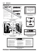
20.1 TO RELEASE PARKING BRAKE MERITOR AXLE 1. Position unit on level ground, lower attachment to approximately one foot from ground, move forward/reverse lever to “Neutral,” apply parking brake and stop engine. 2. Block all wheels to prevent inadvertent movement. Figure 20-2 RELEASE SCREW A GUIDE PIN A SPACER RELEASE SCREW SECTION A A 3. Working one side at a time, remove three release screws and spacers from side of differential housing (located at 12 o’clock, 4 o’clock and 8 o’clock). 4.
20.2 CARRARO AXLE 1. If possible position unit on level ground lower attachment to approximately one foot from ground, move forward/reverse lever to “Neutral”, apply parking brake and stop engine. 2. Chock all wheels to prevent inadvertent movement. Figure 20-3 RELEASE SCREW (12 o’clock position) FRONT OF MACHINE RELEASE SCREW (4 o’clock position) RELEASE SCREW (8 o’clock position) 3.
E AG P IS TH T LEF Y ALL N TIO N E INT K.
INSPECTION AND MAINTENANCE LOG This page is provided so you may record all inspections and maintenance on your machine. Record the date, hourmeter reading and a detailed description of the procedure in the comment area. Record all information in the Owner/Operator Manual, stored in the operator’s cab. Date Hourmeter Reading Form No.
INSPECTION AND MAINTENANCE LOG Date Hourmeter Reading Comments
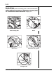
HAND SIGNALS Standard Signals - When handler work conditions require hand signals, they shall be provided or posted conspicuously for the use of both signalman and operator. No handler motions shall be made unless signals are clearly understood by both signalman and operator. Special Signals - When signals for auxiliary equipment functions or conditions not covered are required, they shall be agreed upon in advance by the operator and signalman.
CALIFORNIA Proposition 65 Warning Diesel engine exhaust and some of its constituents are known to the State of California to cause cancer, birth defects and other reproductive harm. CALIFORNIA Proposition 65 Warning Battery posts, terminals and related accessories contain lead and lead compounds, chemicals known to the State of California to cause cancer and birth defects or other reproductive harm. Wash hands after handling.