® ® SERVICE MANUAL ® 522D 534D-6 524D 534D-6T 9133-4002 July 2002 522D 524D Starting S/N 0277001 534D-6 534D-6T Starting S/N 0588001 CORPORATE OFFICE GRADALL DIVISION JLG INDUSTRIES, INC. 1 JLG DRIVE McConnellsburg, PA 17233-9533 USA Telephone: (717) 485-5161 Fax: (717) 485-6417 JLG INDUSTRIES, INC. 406 Mill Avenue S.W.
® ® OWNER/OPERATOR MANUAL ® 522 534D-6 524 534D-6T 9133-4037 July 2002 522D 524D Starting S/N 0277001 534D-6 534D-6T Starting S/N 0588001 Form #20045 Revised Issue 12/00 CORPORATE OFFICE GRADALL DIVISION JLG INDUSTRIES, INC. 1 JLG DRIVE McConnellsburg, PA 17233-9533 USA Telephone: (717) 485-5161 Fax: (717) 485-6417 JLG INDUSTRIES, INC. 406 Mill Avenue S.W.
Open Center HYDRAULIC POWER BRAKE VALVE MICO Incorporated 1911 Lee Boulevard (Zip Code 56003-2507) P.O. Box 8118/North Mankato, MN U.S.A. 56002-8118 Phone: (507) 625-6426 Facsimile: (507) 625-3212 Form No. 81-460-047 Revised 10/95 MICO West Division 701 East Francis Street (Zip Code 91761-5514) P.O. Box 9058/Ontario, CA U.S.A. 91762-9058 Phone: (909) 947-4077 Facsimile: (909) 947-6054 Printed in U.S.A.
TABLE OF CONTENTS System Schematic...........................................................................................................................Page 2 Representative Performance Data......................................................................................................Page 2 Description and Operation of Power Brake Valve......................................................................Pages 3, 4 & 5 External Dimensional Views...................................................
DESCRIPTION AND OPERATION OF THE MICO OPEN CENTER HYDRAULIC POWER BRAKE VALVE The MICO Open Center Brake Valve will provide hydraulic power braking when installed in an open center hydraulic circuit. It can be used in conjunction with other hydraulic devices such as power steering, also installed in the same circuit. Using a single pump to provide flow and pressure, the brake valve should be installed in the system circuitry, in series, between the pump relief valve and the other hydraulic devices.
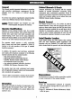
Hydraulic System Pressure Equal to Brake Line Pressure RETURN LINE PRESSURE Inlet Port From Pump Land “B” BRAKE LINE PRESSURE FIGURE 4 Land “C” Land “A” CONTROLLED PRESSURE To Brake Pedal Return Line Pressure Orifice Reaction Chamber Flow Thru Port Schematic of Brake Valve in Manual Operation RETURN LINE PRESSURE FIGURE 5 Inlet Port From Pump BRAKE LINE PRESSURE Orifice Manual Brake Actuating Sleeve To Brake Pedal Pressure Regulating Sleeve Flow Thru Port is released.
one-half the brake line pressure, the PRESSURE REGULATING SPOOL shifts a minute amount and the pressure is regulated across LAND “A” and LAND “B” (Figure 4). If the pressure required by the brake valve is lower than that required by the power steering, the power steering will not normally interfere with the operation of the brake (Figure 4).
THREE OPEN CENTER HYDRAULIC POWER BRAKE VALVE DESIGNS PRIMARY CUP DESIGN The Primary Cup Design uses a residual valve. This valve will maintain a pressure of 12 - 20 PSI in the brake lines when the pedal is released. When used in drum brake systems this low pressure aids in preventing air from entering the brakes when the vehicle is at rest. RING SEAL DESIGN The Ring Seal Design is used mainly in disc brake systems.
SPECIFICATIONS CHART Brake Port Pressure Port Flow Thru Port Return Port Brake Line Pressure (with power) Flow Capacity * 06-460-520 1/2-20 UNF SAE No. 10 Complete unit replaced by 06-460-658 SAE No. 10 1/2-14 NPTF 1850 psi ± 50 psi 3-24 gpm 06-460-522 9/16-18 UNF SAE No. 10 1/2-20 UNF * 06-460-550 SAE No. 10 Complete unit replaced by 06-460-656 * 06-460-560 1/2-20 UNF SAE No. 8 Complete unit replaced by 06-460-656 9/16-18 UNF * 06-460-570 SAE No.
OPEN CENTER HYDRAULIC BRAKE VALVE PRIMARY CUP DESIGN (Refer to Figure 10) Disassembly 1. Remove boot (item 1) and pressure regulating spring assembly (item 2). CAUTION: Pressure regulating spring assembly has been set at the factory and should never be disassembled, re-adjusted or interchanged with another valve. 2. Separate end cap (item 21) from housing (item 11). CAUTION: Care must be taken as end cap is under tension of spring (item 19). Remove gasket (item 14). 3.
Items included in Repair Kit 06-459-002 FIGURE 10 Model Number Repair Kit 06-460-520 06-460-522 06-460-550 06-460-560 06-460-570 06-460-580 06-460-588 06-460-610 06-460-620 06-460-650 06-460-680 06-460-686 06-459-002 06-459-002 06-459-002 06-459-002 06-459-002 06-459-002 06-459-002 06-459-002 06-459-002 06-459-002 06-459-002 06-459-002 (9)
OPEN CENTER HYDRAULIC BRAKE VALVE RING SEAL DESIGN (Refer to Figure 11) Disassembly 1. Remove boot (item 1) and pressure regulating spring assembly (item 2). CAUTION: Pressure regulating spring assembly has been set at the factory and should never be disassembled. 2. Separate end cap (item 21) from housing (item 11). CAUTION: Care must be taken as end cap is under tension of spring (item 20). Remove gasket (item 14). 3. Remove piston & poppet assembly (item 17) and spring (item 20) from end cap (item 22).
Items included in Repair Kit 06-459-010 Items included in Repair Kit 06-459-020 FIGURE 11 NOTE: Residual Valve (item 21) is only found in Model 06-460-566.
OPEN CENTER HYDRAULIC BRAKE VALVE SLIDING PISTON DESIGN (Refer to Figure 12) Disassembly 1. Remove boot (item 1) and pressure regulating spring assembly (item 2). CAUTION: Pressure regulating spring assembly has been set at the factory and should never be disassembled. 2. Separate end cap (item 20) from housing (item 3). CAUTION: Care must be taken as end cap is under tension of spring (item 18). 3. 4. 5. 6. 7. Remove gasket (item 6).
Items included in Repair Kit 06-459-020 FIGURE 12 Model Number 06-460-642 06-460-684 Repair Kit 06-459-020 06-459-020 (13)
GENERAL SERVICE DIAGNOSIS With Engine Off -PEDAL GOES TO FLOOR 1. Brake not adjusted 1. Check adjustment 2. Air in system 2. Bleed brakes 3. Inoperative brakes 3. Check brakes 4. Blown hydraulic line 4. Check brake line 5. Worn out primary cup 5. Check by making sure brakes are properly adjusted, in good operating condition, and system well bled. If pedal continues to go to the floor, service brake valve. SPONGY PEDAL 1. Air in system 1. Bleed brakes PEDAL IS FIRM BUT STOPS TOO NEAR FLOOR 1.
PRESSURE BLEEDING PROCEDURE 1. Refer to Figure 13. Install a small BLEEDER BY-PASS LINE as shown. A 1/4” size line or hose is sufficient. 2. Start engine and allow enough time to pass for the system to become filled and thoroughly flushed with oil. 3. It is necessary to develop between 50-200 PSI at the inlet to brake valve. A method to throttle the oil will be needed if the system does not already have a secondary hydraulic device downstream from the brake valve.
MICO has made every attempt to present accurate information in catalogs, brochures and other printed material. MICO can accept no responsibility for errors from unitentional oversights that may exist. Due to a continuous program of product improvement, both materials and specifications are subject to change without notice or obligation.
Service Notes This publication provides maintenance and service procedures for Meritor PRA 352 series planetary axles. The information contained in this publication was current at the time of printing and is subject to revision without notice or liability. 1. You must understand all procedures and instructions before you begin maintenance and service procedures. 2. You must follow your company’s maintenance and service guidelines. 3.
47 PRA 352 – Trumpet Variation No.
PRA 352 – Trumpet Variation No.
PRA 352 – Trumpet Variation No.
PRA 352 – Trumpet Variation No.
PRA 353/383 68 67 65 66 64 62 82 83 81 60 63 61 69 81 80 73 71 72 75 74 57 70 77 37 43 42 89 54 46 55 50 48 37 38 40 45 53 85 36 44 84 86 56 52 58 36 37 49 47 79 59 78 39 41 87 88 51 58 89 14 20 12 11 8 13 19 18 26 27 28 29 4 3 15 16 24 17 6 5 79 12 60 80 81 82 78 69 61 63 10 31 23 22 30 77 76 70 74 7 75 73 72 2 71 9 11 81 83 62 64 66 32 33 59 25 67 65 34 21 68 36 37 35 36 38 37 42 39 41 37 43 89 54 55 50 46 51 V 52 40 49 44 56 53
PRA 353/383 Item 1 2 3 4 5 6 7 8 9 10 11 12 13 14 15 16 17 18 19 20 21 22 23 24 25 26 27 28 29 30 31 32 33 34 35 36 37 38 39 40 41 42 43 44 45 Item Description Center Housing Differential Case Side Gear Thrust Washer Pinion Gear Thrust Washer Differential Pinion Shaft Pinion Shaft Lock Pin Washer Capscrew Bearing Cone Bearing Cup Spiral Gear and Pinion Differential Case Shim Pinion Cage Bearing Cup Bearing Cone Drive Pinion Shim Bearing Cup Bearing Cone Motor Adapter Flange Driven Sleeve Drive Sleeve Snap
PROA 352/382 (With Mechanical Drive Option) 17 16 4 36 98 99 20 18 97 1 43 19 24 26 27 2 14 13 32 23 3 15 22 37 40 7 39 94 12 38 99 93 11 8 41 9 21 34 95 10 35 4 28 6 33 5 43 96 30 45 58 31 44 42 57 52 56 54 59 51 55 29 85 53 77 49 60 84 50 86 62 63 46 65 61 47 66 83 67 82 68 48 79 87 64 89 100 78 72 88 64A 73 90 92 91 76 69 80 81 74 70 71 VII
PROA 352/382 (With Mechanical Drive Option) Item Item Description 1 2 3 4 5 6 7 8 9 10 11 12 13 14 15 Main Housing Bushing Trunnion Oil Seal Differential Case Assembly Differential Case Capscrew Differential Case Washer Side Gear Friction Discs Shim Pack Friction Drive Disc Friction Driven Discs Compression Discs Thrust Washer Pinion Gear Pinion Gear Thrust Washer Spider 16 17 18 19 20 21 22 23 24 25 26 27 28 29 30 31 32 33 34 35 36 37 38 39 40 41 42 43 44 45 46 47 48 49 50 51 Gear Capscrew Washer Gea
PROA 352/382 IX
PROA 352/382 Item 1 2 3 4 5 6 7 8 9 10 11 12 13 14 15 16 17 18 19 20 21 22 23 24 25 26 27 28 29 30 31 32 33 34 35 36 37 38 39 40 41 42 43 44 45 46 47 48 Item Description Center Housing Bushing Trunnion Oil Seal Lubrication Fitting Level Plug Drain Plug Vent Plug Hydraulic Line Bleeder Cover Capscrew M8x1,25x16,0 Differential Case Assembly Washer Capscrew M10x1,5x80,0 Drive Disc Driven Friction Disc Clutch Disc Shim Compression Disc Thrust Washer Side Gear Thrust Washer Pinion Gear Spider Spiral Gear & Pin
Table of Contents Section 1: Introduction Description ......................................................................................................................................................1 Identification Section 2: Removal and Disassembly Remove Axle ..................................................................................................................................................2 Disassemble Ball and Ramp Brake Disassemble Trumpet Assembly ..................................
Table of Contents Assemble Hydraulic Apply Brake Housing Assembly ..................................................................................38 Hydraulic Apply Brake Housing Functional Test Assemble Three Function Brake Housing Assembly ....................................................................................39 Assemble Ball and Ramp Brakes, Brake Discs, Reaction Plate and Pins ....................................................
Section 1 Introduction Description Identification The Meritor PRA 352 Series Planetary Axle is a double reduction single speed unit that has: A tag on the main housing correctly identifies basic axle specifications. • • A hypoid or spiral pinion and ring gear set When ordering parts, be sure to specify information stamped on the name plate. This information will allow easy identification of correct parts.
Section 2 Removal and Disassembly Remove Axle ! WARNING To prevent serious eye injury, always wear safe eye protection when you perform vehicle maintenance or service. ! WARNING Support vehicle with safety stands. Do not work under a vehicle only supported by jacks. Jacks can slip or fall over and cause serious personal injury.
Section 2 Removal and Disassembly ! CAUTION Loosen and remove brake cylinder capscrews alternately to avoid spring load damage to parts. 5. Disassemble brake cylinder assembly. Remove brake release capscrew. Loosen and remove brake cylinder capscrews alternately to avoid spring load to be supported by only one capscrew. 6. Remove spring, piston and O-ring seals. Do not cut or scratch them. 7. Clean cylinder and brake support surfaces. Do not damage ground surfaces. 8.
Section 2 Removal and Disassembly Disassemble Planetary System and Axle Shaft NOTE Before removing planetary gears, place housing in horizontal position or place cloth between pinion gear flange and housing flange to keep rollers from falling down into housing. To avoid mixing them, be sure to put rollers and spacers of each planetary gear in separate plastic bags. 4. Remove pinion gear flange. Lift it through planetary gear pins. 5. Remove axle shaft assembly and cone bearing. If necessary, use press.
Section 2 Removal and Disassembly Disassemble Hydraulic Apply Wet Disc Brake Disassemble Three Function Wet Disc Brake 1. Remove piston return spring capscrews. NOTE 2. Remove return springs. Do not disassemble brake piston unless necessary. 3. Remove brake piston assembly. Figure 2.9. Figure 2.9 1. Remove return spring capscrews with 4 mm Allen wrench. Remove return springs and washers. Figure 2.11. Figure 2.11 ! CAUTION Ground oil seal surfaces must be properly protected to avoid damage.
Section 2 Removal and Disassembly ! ! WARNING • Use a special tool or press to compress the brake assembly to avoid serious personal injury from the spring pressure. • Observe all WARNINGS and CAUTIONS provided by the press manufacturer concerning press operation to avoid serious personal injury and damage to components. CAUTION Before removing action plate and other parts, mark the original assembly positions of all brake piston assembly parts. This procedure will make reassembly easier. 6.
Section 2 Removal and Disassembly 8. Use sand paper on piston surfaces if they have nicks or hits. Figure 2.17. 5. Depending on ring gear position, remove pinion bearing cage capscrews. Figure 2.17 6. Remove pinion bearing cage assembly from main housing. Figure 2.19. 7. Remove drive sleeve and snap ring. Figure 2.19. Figure 2.19 Disassemble Main Housing 1. Remove adjusting nut capscrew lock. 2. Remove adjusting nut capscrew and adjusting nut. DRIVE SLEEVE & SNAP RING 8.
Section 2 Removal and Disassembly 1. Before disassembling differential case, mark position of both halves and spider cross for easier reassembly. Figure 2.21. 5. If differential case is “integral,” remove differential pinion axle lock capscrew and differential pinion axle. Then turn side gears and remove differential pinions, side gears and washers. Figures 2.23, 2.24 and 2.25. Figure 2.21 Figure 2.23 Disassemble Differential Case 2. Remove differential case capscrews. Figure 2.24 3.
Section 2 Removal and Disassembly 6. If necessary, separate ring gear from differential case. Remove capscrews and washers that fasten ring gear. With brass hammer, tap ring gear to separate it from differential case. Figures 2.26 and 2.27. 7. If differential case has two halves, remove ring gear with a press after capscrews have been removed (Figure 2.26). Use appropriate metal or wood supports. Figure 2.28. Figure 2.28 Figure 2.26 SUPPORTS Figure 2.27 8.
Section 2 Removal and Disassembly Disassemble Pinion Bearing Cage 1. If pinion bearing cage was not removed, hold yoke, flange or splined sleeve with appropriate holder to remove pinion nut. Figure 2.32 If pinion bearing cage was already removed, place it on main housing and fasten with two capscrews. ! CAUTION To avoid oil leaks, be careful not to damage the mounting surface of the bearing cage. 3. Remove pinion oil seal. Pry at several points around circumference between seal, flange and bearing cage.
Section 2 Removal and Disassembly ! CAUTION Figure 2.37 Do not use pry bar to remove bearing cage from carrier. A pry bar can damage bearing cage, shims and main housing. 5. Remove pinion bearing cage and shims from main housing. If bearing cage is tight within the main housing, hit bearing cage at several points around flange area with leather, plastic or rubber mallet. Figure 2.36. Figure 2.36 NOTE The inner bearing cone and bearing spacer will remain on the pinion shaft. 9.
Section 2 Removal and Disassembly 10. If pinion bearings need to be replaced, remove inner bearing cone from drive pinion with press or bearing puller. Puller must fit under inner face of cone to remove cone correctly without damage. Figure 2.40. Figure 2.40 NOTE If bearing cup is changed, the bearing cone must also be replaced. The cup and cone must come from the same manufacturer.
Section 3 Prepare Parts for Assembly Clean Ground and Polished Parts ! WARNING Clean Axle Assemblies • A complete axle assembly can be steam cleaned on the outside to remove dirt. • Before the axle is steam cleaned, close or put a cover over all openings in the axle assembly. Examples of openings are breathers and hydraulic inlets. To prevent serious eye injury, always wear safe eye protection when you perform vehicle maintenance or service.
Section 3 Prepare Parts for Assembly Inspect Tapered Roller Bearings Inspect the cup, cone, rollers and cage of all tapered roller bearings in the assembly. If any of the following conditions exist, the bearing must be replaced: • The center of the large diameter end of the rollers are worn level with, or below the surface. • The center of the large diameter end of the rollers are worn to a sharp edge. Figure 3.1. • Deep cracks or breaks in the cup, cone inner race or roller surfaces.
Section 3 Prepare Parts for Assembly • Damage on the cup and cone inner race surfaces that touch the rollers.Figure 3.5. Figure 3.5 SPALLING & FLAKING Inspect Main Differential Assembly Parts that are damaged must be replaced. Inspect the following parts for wear or stress. Figure 3.6. Figure 3.6 Inspect Hypoid Pinion and Ring Gear Sets ! • • CAUTION Hypoid drive pinions and ring gears are machined in matched sets.
Section 3 Prepare Parts for Assembly Inspect Main Housing • For fractures and burrs in machined areas. Inspect Yoke • For wear at seal journal area. Replace yoke, flange or sleeve if either shows too much wear at seal journal area. Inspect Planetary System Parts • For existence of cracks, pitting, breaks or sharp edges on planetary gear teeth, planetary gear axles and rollers. Inspect Brakes • For condition of friction discs, brake piston springs and internal brake housing surfaces.
Section 3 Prepare Parts for Assembly Liquid Adhesive Reassembly Meritor uses the following liquid adhesives to retain threaded fasteners: • Check the type of liquid adhesive to be used and where the adhesive is to be applied. • In threaded holes where fasteners did not require removal, check each one for tightness by applying the minimum amount of specified torque. • If fasteners do not rotate, they are tightened properly.
Section 3 Prepare Parts for Assembly Apply Silicone Gasket Material Liquid gasket material used by Meritor: • • Loctite FAG 3 5. Assemble components quickly to permit gasket material to compress evenly between parts. Figure 3.8 Neutral Silicon, Dow Corning 768 or Rhodia 567/666 • • 0.125" (3.18 MM) DIAMETER SILICONE GASKET MATERIAL BEAD Three Bond 1134 Loctite 515 ! WARNING Small amounts of acid vapor are present when applying some gasket materials.
Section 3 Prepare Parts for Assembly ! ! WARNING To avoid serious personal injury, trichloroethylene must not come in contact with your skin. Do not smoke and avoid breathing vapors in closed rooms without ventilation. Do not use trichloroethylene near flames, welding operations or hot surfaces exceeding 900°F (482°C). 1. Remove any dust, oil or foreign material from Toric ring (2), lodging ramps (4, 7), ring retention lips (3, 8), oil seal ring (1) and ring bore (5).
Section 3 Prepare Parts for Assembly 5. Verify mounting distance (A) in at least four places spaced 90 degrees apart. The difference in the mounting distance (A) around ring cannot be more than 0.04 inches (1 mm). Figure 3.15. NOTE Do not use any liquid that leaves a film of oil or does not evaporate quickly. 3. Place installation tool (9) under oil seal ring with Toric ring (2). Submerge ring in receptacle filled with trichloroethylene until entire surface of Toric ring is wet. Figure 3.13. Figure 3.
Section 3 Prepare Parts for Assembly ! • CAUTION Misalignment or a twisted Toric ring may cause leakage in the DUO-CONE oil seal. If installation was not correct, remove oil seal from bore and repeat steps 3-6. • A Toric ring must never slide on any ramp of oil seal ring or bore. To prevent sliding, wait at least two minutes for trichloroethylene to evaporate before continuing with installation. When in the correct position, Toric ring must roll only on ramps.
Section 3 Prepare Parts for Assembly • Warped ring can cause irregular pressure on ring surface resulting in oscillating movements of oil seal. • Different pressures on oil seal surfaces can cause seepage, wear and leaks. • Oscillating oil seals allow dirt to enter. Figure 3.21 shows an incorrect installation of an oil seal in its mounting position. The upper bore is stopped and the lower lodge is rotating. Figure 3.21 CL X B A Y X Figure 3.
Section 4 Assembly and Installation Assemble Differential Case ! WARNING To prevent serious eye injury, always wear safe eye protection when you perform vehicle maintenance or service. 4. Apply Loctite 271 or Three Bond 1305 adhesive to ring gear fasteners. See Section 3, “Liquid Adhesive.” Install ring gear fasteners and fasten with the specified torque, 66-75 lb-ft (90-100 N•m). Figure 4.1. T Figure 4.1 1. Apply specified lubricant on all parts of differential case assembly before installation.
Section 4 Assembly and Installation NOTE For limited slip differential, go to step 12. 7. Install spider cross, differential pinions and washers on original assembly position. Figure 4.3. d. Install differential pinion axle and lock capscrew. Fasten capscrew to specified torque 17-23 lb-ft (23-31 N•m). T 8. Install other side gear over spider and differential pinions. Figure 4.5. Figure 4.5 Figure 4.3 SPIDER a.
Section 4 Assembly and Installation 10. Apply Loctite 271 or Three Bond 1305 liquid adhesive to capscrews. Install four capscrews into case halves equally spaced and tighten to 48-64 lb-ft (64-87 N•m). T 11. Install other capscrews into case halves. Tighten the capscrews to 48-64 lb-ft (64-87 N•m). T 12. Assemble Limited Slip Differential Case. d. Place disc pack stack in vise. Use micrometer to determine “D”, the height (thickness) of limited slip disc stack (includes thrust washer and compression disc).
Section 4 Assembly and Installation f. Place removed plain half side gear on top as shown in Figure 4.10. Use depth gauge to determine “A”, distance from differential case half flange to backside of differential side gear. Take four readings. Average readings for result. Figure 4.10. g. Determine clearance dimension: B-A=(C-D)-A. Clearance dimension must be greater than 0.05 mm and less than 0.15 mm. h. Use proper shim thickness to achieve clearance specified in step G. i.
Section 4 Assembly and Installation 2. Attach torque wrench to the tool nut and rotate differential gears. As differential rotates, read torque value indicated on dial. Figure 4.13. T Figure 4.13 2. Support bearing cage with metal or wood blocks. 3. Press the bearing cup into bore of bearing cage until cup is flat against bottom of bore. Use correct size sleeve to install bearing cup. NOTE Use same procedure for both bearing cups. 4. Put drive pinion in press.
Section 4 Assembly and Installation 9. Install outer bearing cone on pinion shaft against spacer. Figure 4.16. NOTE Do not install pinion oil seal in bearing cage before bearing preload adjustment. Continue adjusting preload of pinion bearings. 5. Use appropriate tool to fasten pinion through yoke, flange or splined sleeve. Figure 4.17. Figure 4.17 10. Press outer cone bearing with 10 ton force and check preload of bearings. Figure 4.16.
Section 4 Assembly and Installation 10. After getting specified preload, remove bearing cage from main housing and disassemble yoke or input flange. ! CAUTION Make sure oil seal lips are clean and free from dirt. Dirt can cause leakage between seal and yoke or flange. 11. Install pinion oil seal with the appropriate tool: a. Apply extreme pressure lithium soap grease to oil seal lips. Figure 4.19. d. Install yoke or flange and pinion nut into pinion. e.
Section 4 Assembly and Installation 2. Record the pinion cone (PC) variation number on the old drive pinion that is being replaced. If the PC variation number cannot be located, assemble the gear set with the shim pack found in step 1. Figure 4.23. Figure 4.23 7. If the new pinion cone number is a minus (–), subtract the number from the standard shim pack thickness that was calculated in step 3 or 4. NOTE The value calculated in step 6 or 7 is the thickness of a new shim pack that will be installed.
Section 4 Assembly and Installation Install Pinion Bearing Cage Assembly on Main Housing NOTE Use minimum of three shims in pack. If pack is made from different thickness shims, install thinnest shims on both sides of pack for maximum sealing. 3. Install two capscrews and washers that fasten bearing cage. Tighten to minimum torque of 67 lb-ft (90 N•m). Figure 4.26. T Figure 4.26 1. Install correct shim pack between bearing cage and main housing. Figure 4.24. Figure 4.24 4.
Section 4 Assembly and Installation 5. If ring gear is mounted on opposite brake housing side, loosen two capscrews that fasten pinion bearing cage. Remove cage and mount it after differential case is assembled. 4. Install differential case assembly. Figure 4.29. Figure 4.29 If ring gear is mounted on brake housing side, install other capscrews that fasten pinion bearing cage. Tighten the capscrews to a torque of 67-91 lb-ft (91-120 N•m).
Section 4 Assembly and Installation 7. Install differential case bearing adjusting nut on brake housing. Figure 4.31. 8. Install pinion bearing cage assembly and shim pack. 9. Check backlash, differential preload and teeth contact. See Section 5, “Adjustments.” Install Differential Housing Assembly into Main Housing (With Adjusting Ring 2 Sides) 1. Install adjusting ring into main housing. 2. Install bearing cup.
Section 4 Assembly and Installation 7. Install pinion bearing cage assembly and shim pack. Figure 4.34. See “Install Pinion Bearing Cage Assembly on Main Housing,” page 31. Figure 4.34 9. Check backlash, differential preload and teeth contact. See Section 5, “Adjustments.” 10. If all adjustments are within specifications, remove brake housing. Apply liquid gasket material to main housing surface. ! WARNING To avoid serious personal injury, be careful when using Loctite.
Section 4 Assembly and Installation 2. Install Duo-Cone oil seal into axle shaft and into axle shaft housing bore as specified on page 18. Figure 4.37. Figure 4.39 44.60 44.80 Figure 4.37 DUO-CONE OIL SEAL ! 3. With a correct size sleeve, use a press to install flange side cone bearing. Install axle shaft into axle shaft housing. Figure 4.37. Assemble Trumpet Assembly ! WARNING WARNING To avoid serious personal injury, be careful when using Loctite.
Section 4 Assembly and Installation ! CAUTION Rollers must come from the same manufacturer and have the same tolerance range. Replace spacers and washers when a new roller is used. 3. Apply grease, Shell-71032 Alvania EP-2 or Texaco - 995 Multifak EP-2, on each gear hole. Install rollers and spacers into planetary gears. Figure 4.40. 5. Install planetary spider and axle shaft bearing adjusting nut. 6. Measure trumpet flange radius.
Section 4 Assembly and Installation 8. Check trumpet assembly preload and subtract value obtained before tightening adjusting nut. Value must be 15-35 lb-in (1.7-4 N•m). T 9. Apply Medium Torque liquid adhesive, Loctite 241 or Three Bond 1334, on adjusting nut lock capscrew threads. Install adjusting nut lock capscrew. Tighten to 17-23 lb-ft (23.0-30.5 N•m). 13. Apply liquid gasket material on contact surfaces of trumpet and ring. Figure 4.46. Figure 4.46 T 10.
Section 4 Assembly and Installation Assemble Hydraulic Apply Brake Housing Assembly NOTE • To assemble three function brake, see page 39. • To assemble ball and ramp brake, see page 43. 6. Apply high torque liquid adhesive, Loctite 271 or Three Bond 1305, to capscrew threads. Install return springs and return spring capscrews. Tighten to 80-115 lb-in (9.0-13.0 N•m). T Figure 4.49. Figure 4.49 1. Check to see if the piston lodging surfaces on brake housing is free of sharp edges, nicks and burrs.
Section 4 Assembly and Installation • • If there are no leaks, proceed to Step 4. Figure 4.51 If there are leaks, disassemble brake housing assembly, find and correct the problem. Repeat Steps 1 to 3. 4. Wait five minutes, then apply 75 to 110 psi (5.1 to 7.6 bar) to the cylinder again. “B” • If there are no leaks, the assembly is assembled correctly. • If there are leaks, find and correct the problem. Repeat the test again. Assemble Three Function Brake Housing Assembly c.
Section 4 Assembly and Installation 2. Lubricate internal brake housing surfaces, inner and outer piston surfaces and oil seal bores with SAE 90 oil. Figure 4.53. Figure 4.55 Figure 4.53 MEDIUM OIL SEAL INNER PISTON 5. Install springs into bores in inner piston. Figure 4.55. For brake with 12 springs, jump one bore each three. Figure 4.55. OUTER PISTON LARGE OIL SEAL SMALL OIL SEAL OIL SAE 90 NOTE Each piston assembly has three different sizes of oil seals: three large, one medium, one small. 3.
Section 4 Assembly and Installation ! 10. Install shim pack into brake housing. Use bolts to align holes. Figure 4.59. WARNING To avoid serious personal injury, be careful when using Loctite. Follow the manufacturer’s instructions for safe use to prevent irritation to eyes and skin. Wash after skin contact. If the Loctite gets in eyes, flush with water for 15 minutes. Have eyes checked by a doctor. Figure 4.59 GUIDE BOLTS 8.
Section 4 Assembly and Installation 14. With piston still compressed, apply 350 psi (24 bar) into parking brake to make sure oil seals fit in bores. Figure 4.61. Figure 4.61 Assemble Ball and Ramp Brakes, Brake Discs, Reaction Plate and Pins 1. Install sun gear. Figure 4.63. Figure 4.63 350 PSI (24 BAR) 15. Keep the parking brake under 350 psi (24 bar) pressure and remove the manual press and guide pins. 16.
Section 4 Assembly and Installation 4. Install stationary disc lock pins. 5. Install reaction plate with lubrication hole on down side of axle. 6. If there is an outer spacer, install it on brake housing surface. Use liquid gasket material. Assemble Three Function Brakes, Brake Discs, Reaction Plate and Pins 1. Lubricate all brake components with same oil specified for axle. See page 53.
Section 4 Assembly and Installation Assemble Three Function Brake Release Bolts and Sleeves Assemble Ball and Ramp Brake Cylinder Assembly and Install on Main Housing 1. Apply Loctite 516 on bolt threads. Figure 4.67. 1. Apply liquid gasket material FAG-3 on brake cylinder surface that fastens to brake cylinder support. Assemble brake cylinder, oil seals, piston and brake cylinder support. Tighten capscrews that fasten brake cylinder support 19-26 lb-ft (26-36 N•m). Figure 4.69. T Figure 4.
Section 4 Assembly and Installation 2. While out of the axle, connect cylinder assembly to hydraulic system. Apply 400 psi (27.6 bar) pressure to compress spring until piston is against brake cylinder. Repeat this operation four to five times to make sure there is no leakage. Figure 4.70. 4. While the cylinder is pressurized with 400 psi (27.6 bar), apply liquid adhesive, Loctite 221 or Three Bond 1341, on threads of brake shaft. Install adjusting nut until it rests against piston.
Section 4 Assembly and Installation 6. After 1.47 inch (37.0 mm) dimension is obtained, apply specified pressure to brake and check the brake torque on pinion as shown in chart. Torque Reduction Disc No. Pressure Torque PRA-382 17.08:1 06 275 psi min (19 bar min) 950-1200 lb-ft (1288.01559.0 N•m) PRA-353 46.00:1 06 275 psi min (19 bar min) 350-500 (474.5678.0 N•m) NOTE To obtain the desired brake torque, fasten or unfasten the adjusting nut. For each 0.
Section 5 Adjustments Check Ring Gear Runout Specification: 0.008 inch (0.20 mm) ! Adjust Pinion and Ring Gear Backlash Specification: 0.005-0.015 inch (0.13-0.38 mm) WARNING 1. Attach dial indicator on mounting flange of carrier. To prevent serious eye injury, always wear safe eye protection when you perform vehicle maintenance or service. 2. Set dial indicator so plunger is against a tooth surface. Figure 5.2. 1. Attach magnetic base dial indicator to mounting flange of main housing. Figure 5.1.
Section 5 Adjustments 6. Loosen one bearing adjusting ring one notch, then tighten opposite ring the same amount to keep differential roller bearing preload. Figure 5.3. Verification Procedure 1. Apply a marking compound to approximately 12 teeth of ring gear. Rotate ring gear so that the 12 gear teeth are next to drive pinion. Figure 5.5. Figure 5.3 Figure 5.5 INCREASE BACKLASH DECREASE BACKLASH NOTE When you adjust backlash, only move ring gear. Do not move drive pinion.
Section 5 Adjustments 3. Compare contact patterns on ring gear teeth to good contact patterns in Figure 5.7. If contact patterns are not satisfactory, go to Incorrect Contact Patterns on this page. Figure 5.7 The location of a good hand-rolled pattern for a used gears set must match wear pattern in ring gear. The contact pattern will be smaller in area than the wear pattern.
Section 5 Adjustments Deep Contact Pattern A deep contact pattern indicates that the drive pinion was installed too far in the carrier. Figure 5.11. Figure 5.11 Variations Along Length of Gear Teeth Adjust backlash of ring gear within specification range to move contact patterns to correct location along length of gear teeth.When toe contact pattern indicates that backlash is very low and gear is too close to drive pinion: Figure 5.13. Figure 5.
Section 5 Adjustments An acceptable contact pattern is centralized between toe and heel along the length of gear teeth. Figure 5.15. Figure 5.15 Replace Lubricant 1. Install and tighten drain plug in central housing and brake housing. T 2. Clean area around fill/level plug. Remove fill/level plug from carrier inspection cover. ! In cases where it is not possible to get a good contact pattern, the contact pattern shown in Figure 5.15 is acceptable.
Section 6 Specifications PRA 352 Series Planetary Drive Axle Oil Change Intervals and Specifications Initial Oil Change 100 operating hours ① or 1240-3100 miles (2000-5000 km) (whichever comes first) Off-Highway Operation Intervals ① Check Petroleum Oil Oil Level Change 250 1,500 operating operating hours hours ① or twice a year (whichever comes first) Synthetic Oil Change — Meritor Specification 0-84 Military Specification — Oil Description Petroleum Base SAE 10W, 20W or 10W/30 ② NOTES: ① The checkin
Section 6 Specifications Nut Lock Special Tool 13.78 in. (350.0 mm) 0.079 in. (20.0 mm) 15.55 in. (395.0 mm) 1.77 in. (45.0 mm) 0.57 in. (14.5mm) 0.078 in. R 2.0 0.197 in. (5.0 mm x 45°) 0.984 in. R 5.0 Ø 0.79 in. (Ø 20.0 mm) Ø 1.97 in. (Ø 50.0 mm) THREAD: Ø 5/8" II UNC Ø 3.15 in. (Ø 80.0 mm) 0.39 in. (10.0 mm x 45°) 1.77 in. (45.0 mm) 2.44 in. (62.0 mm) 4.53 in. (115.0 mm) Ø 0.709 in. (Ø 18.0 mm) 0.079 in. (2.0 mm) in. 47 m) 0.5 .9 m Ø 3 1 8 (Ø 13. 30°±10' Ø 3.86 in. (Ø 98.
Section 6 Specifications PROA 352/382 (With Mechanical Drive Option) 4 14 11 10 15 5 16 1 3 6 13 8 19 7 17 18 2 9 12 54
Section 6 Specifications Torque Chart - PROA 352/382 ITEM 1 2 3 4 5 6 7 8 9 10 11 DESCRIPTION/THREAD Pinion Nut - M24 x 1.5-6H Nut (Stud - Center Housing) M14 x 1.5-6H Capscrew (Differential Case) M10 x 1.5-8G Capscrew (Spiral Gear) M10 x 1.0-6G Capscrew (Pinion Cage) M12 x 1.75-8G Capscrew (Lock Adjuster Ring) M6 6G Capscrew (Adjusting Nut Lock) M8 x 1.25-6G Capscrew (Brake Housing) M8 x 1.25-6G Capscrew (Brake Releaser) M12 x 1.75-6G Capscrew (Flange Adapter) .
Section 6 Specifications PRA 352 – Trumpet Variation No.
Section 6 Specifications Torque Chart - PRA 352 ITEM 1 2 3 4 5 6 7 8 9 10 11 12 13 DESCRIPTION/THREAD Pinion Nut - M24 x 1.5-6H Capscrew (Center Housing) - M14 x 1.5-6G Nut (Stud - Center Housing) - M14 x 1.5-6H Capscrew (Differential Case) - M10 x 1.5-6G Capscrew (Spiral Gear) - M10 x 1.0-6G Capscrew (Pinion Cage) - M12 x 1.75-6G Capscrew (Lock - Adjuster Ring) - M6-6G Capscrew - Adjusting Nut Lock - M8 x 1.25-6G Bolt - Return Spring - M6 x 1.0-6G Capscrew (Planetary Pinion Axle) - M10 x 1.
Section 6 Specifications PROA 352 G2H, G2M 5 17 16 21 20 2 18 8 4 19 22 7 6 10 11 1 14 13 10 11 14 15 9 2 12 13 3 17 58
Section 6 Specifications Torque Chart - PROA 352, G2H, G2M ITEM 1 2 3 4 5 6 7 8 9 10 11 DESCRIPTION/THREAD Pinion Nut - M24 x 1.5-6H Capscrew (Center Housing) M14 x 1.5-6G Nut (Stud - Center Housing) M14 x 1.5-6H Capscrew (Differential Case) M10 x 1.5-6G Capscrew (Spiral Gear) M10 x 1.0-6G Capscrew (Pinion Cage) M12 x 1.75-6G Capscrew (Lock Adjuster Ring) M6 6G Capscrew (Adjusting Nut Lock) M8 x 1.25-6G Capscrew (Brake Housing) M8 x 1.25-6G Capscrew (Brake Cylinder Support) M8 x 1.
IMPLEMENT CIRCUIT PERFORMANCE CHECKS m a t e r i a l h a n d l e r Covers all C & D Series Material Handlers A ® Company ® Form No. 29813 Issue Date 4/99 Rev.
REVISIONS This page is provided so you may determine that this Manual is complete and current with respect to Gradall Engineering Specifications. Page Date N/A Jan/01 Revision Updated original manual to include all C and D-Series Implement Functions.
TABLE OF CONTENTS REVISIONS ..................................................... TABLE OF CONTENTS INTRODUCTION ............................................... Orientation Preparing the Material Handler for Service Additional Maintenance/Service Precautions Hydraulic System Precautions Required Tools for Testing/Adjusting SAFETY NOTE ON USING THE MANUAL HYDRAULIC OIL RESERVOIR ............................. HYDRAULIC FILTER CONDITION ........................ ENGINE SPEED ....................................
INTRODUCTION This Manual details Implement Circuit Performance Checks and Adjustments for all Gradall C & D Series Material Handlers. Use the Manual in conjunction with the appropriate Owner/Operator Manual and the appropriate Hydrostatic Drive Performance Checks Manual. Make sure you read the entire Manual before testing, adjusting, or troubleshooting on any Gradall Material Handler. Make sure you understand and comply with all procedures as outlined in the Manual.
HYDRAULIC SYSTEM PRECAUTIONS • Make sure the hydraulic fluid level in the reservoir is maintained at the proper level. If the fluid level drops unduly, the pumps will be starved and will be destroyed almost immediately. • Hydraulic fluid must be completely free of contamination at all times. Contaminated hydraulic fluid can severely damage hydraulic components. It may even destroy the entire hydraulic system.
SAFETY THE FOLLOWING SYMBOLS CALL YOUR ATTENTION TO IMPORTANT SAFETY NOTICES: ! DANGER This symbol indicates an extreme hazard which will result in high probability of death or serious injury if proper precautions are not taken. ! WARNING This symbol indicates a hazard which could result in death or serious injury if proper precautions are not taken. ! CAUTION This symbol indicates a hazard which may result in injury or damage to equipment or property if proper precautions are not taken.
NOTE ON USING THE MANUAL This Manual contains a series of tests designed to assess the performance of various implement circuits on the Material Handler. In every instance, there are certain basic precautions and steps you should take before conducting the test. These precautions are outlined in the “Introduction” under the heading, “Preparing the Material Handler for Service”.
HYDRAULIC OIL RESERVOIR • CHECK 1. The hydraulic oil level gauge is on the outside of the reservoir. 2. Proper level is to “Full” mark in the sight gauge. 3. Do not operate the machine if below “Add” line. 4. Check level with boom fully retracted and forks on the ground. HYDRAULIC OIL LEVEL SIGHT GAUGE • ADJUST 1. Refer to the “Lubrication Chart” in the appropriate Owner/ Operator Manual for oil specifications. NOTE! The system contains approximately 45 gallons of hydraulic oil.
HYDRAULIC FILTER CONDITION • • • SET UP 1. With the park brake engaged and the transmission in “Neutral”, start the material handler. 2. Warm the hydraulic oil to 100°F by stalling the “Crowd-In” function at full engine speed. CHECK 1. After the hydraulic oil reaches operating temperature (minimum 100°F), check the condition of the hydraulic filter. You will need an assistant. 2.
ENGINE SPEED • SET UP 1. With the park brake engaged and the transmission in “Neutral”, start the material handler. 2. Raise the boom high enough to gain access to the engine compartment. • CHECK 1. Install an adequate tachometer and check the engine speed (RPM). 2. At low idle, engine speed should be 800-900 RPM. 3. At full throttle, engine speed should be 2500 +150/-0 RPM. • RAISE THE BOOM HIGH ENOUGH TO GAIN ACCESS TO THE ENGINE COMPARTMENT ADJUST 1.
CHARGE PRESSURE (Also used as Pilot Pressure on Joystick Machines) • SET UP 1. Install a 1,000 PSI pressure gauge, hose and adapter on the charge pump test port. 2. Make sure the gauge can be observed in the operator’s cab. NOTE! For more details, see page 73 of the Material Handler Hydraulic System Manual (Form No. 29101). NOTE! The location of the charge pump test port varies by machine vintage. C SERIES: CHARGE PUMP TEST PORT D SERIES: CHARGE PUMP TEST PORT (HOSE ATTACHED) • CHECK 1.
STEERING CIRCUIT • SET UP 1. Install a 10,000 PSI gauge, hose and adapter to the test port in the outlet tube of the main implement pump. Make sure you can see the gauge from the operator’s cab. NOTE! The location of the main implement test port varies by machine vintage. 522, 524, 532C-6, 534C-6 and 534C-6T MAIN IMPLEMENT TEST PORT ALL OTHER MODELS MAIN IMPLEMENT TEST PORT 2. With the park brake engaged and the transmission in “Neutral”, start the material handler.
MAIN CONTROL VALVE PUMP RELIEF • SET UP 1. Install a 10,000 PSI gauge, hose and adapter to the test port in the outlet tube of the main implement pump. Make sure you can see the gauge from the operator’s cab. NOTE! The location of the main implement test port varies by machine vintage. 522, 524, 532C-6, 534C-6 and 534C-6T MAIN IMPLEMENT TEST PORT ALL OTHER MODELS MAIN IMPLEMENT TEST PORT 2. With the park brake engaged and the transmission in “Neutral”, start the material handler.
TILT CIRCUIT RELIEF VALVES • SET UP 1. Install a 10,000 PSI gauge, hose and adapter to the test port on the outlet tube of the main implement pump. Make sure you can see the gauge from the operator’s cab. NOTE! The location of the main implement test port varies by machine vintage. 522, 524, 532C-6, 534C-6 and 534C-6T MAIN IMPLEMENT TEST PORT ALL OTHER MODELS MAIN IMPLEMENT TEST PORT 2. With the park brake engaged and the transmission in “Neutral”, start the material handler. • CHECK 1.
CROWD CIRCUIT EXTEND RELIEF VALVE • SET UP 1. Install a 10,000 PSI gauge, hose and adapter to the test port on the outlet tube of the main implement pump. Make sure you can see the gauge from the operator’s cab. NOTE! The 534C-9, 534C-10, 534D-9 and 534D-10 are the only C or D Series Material Handlers with a Crowd Circuit Extend Relief Valve. MAIN IMPLEMENT TEST PORT 2. With the park brake engaged and the transmission in “Neutral”, start the material handler. • CHECK 1.
AUXILIARY CIRCUIT RELIEF VALVES • CHECK # 1 1. Inspect the quick-disconnect fittings at the boom head for signs of leakage. 2. Replace any leaking fittings. • CHECK # 2 1. Install a 10,000 PSI gauge, hose and adapter to the test port on the outlet tube of the main implement pump. Make sure you can see the gauge from the operator’s cab. BOOM-HEAD QUICK-DISCONNECT FITTINGS NOTE! The location of the main implement test port varies by machine vintage.
SERVICE BRAKE VALVE • SET UP 1. Install a 10,000 PSI gauge, hose and adapter to the test port on the service brake system. Make sure you can see the gauge from the operator’s cab. NOTE! The Service Brake Test Port may be in one of three different locations: 1. Under the cab by the Brake Valve. 2. Along the left-hand frame rail in the Battery Compartment. 3. In the Battery Compartment behind the differential (see picture). D-SERIES SERVICE BRAKE TEST PORT 2.
APPENDIX A: CYCLE TIMES FOR FUNCTIONS 1. Position the handler safely, in a level, open area, well away from traffic lanes, buildings, other equipment or personnel. 2. Position the handler so that all cylinders may bottom out in both directions. 3. Run the engine at full throttle (2500 RPM) during testing. C-Series Cycle Times FUNCTION Boom Up (fully retracted) Boom Down (fully retracted) Boom Extend (level) Boom Retract (level) Attachment Tilt Up Attachment Tilt Down 522 & 524 10.00 7.00 7.00 10.00 3.
©Gradall, 2000 The information contained in this Manual is protected by copyright. Unauthorized reproduction of this Manual, in whole or in part, in any form whatsoever, is strictly prohibited. Specifications are correct at time of publication. However, Gradall reserves the right to make any necessary changes without prior notice.
Steering Control Units, Char-Lynn Most steering problems can be corrected if the problem is properly defined. The entire steering system should be evaluated before removing any components. The steering control unit is generally not the cause of most steering problems. The following is a list of steering problems along with possible causes and suggested corrections. Problem Possible Cause Correction 1. Slow steering, hard steering, or loss of power assist. Worn or malfunctioning pump.
Problem Possible Cause Correction Steering control unit meter has a lack of oil. This can happen on problem. start-up, after repair, or long periods of non use. No flow to steering unit can be caused by: 1. Low fluid level. 2. Ruptured hose. 3. Internal steering control unit damage due to thermal shock*. Usually starting engine will cure problem. 9. Free Wheeling-Steering wheel turns with slight resistance but results in little or no steered wheel action. Piston seal blown out. Determine cause.
Cyclopac® Service Procedures Proper air cleaner servicing results in maximum engine protection against the ravages of dust. Proper servicing can also save time and money by maximizing filter life and dust cleaning efficiency. Two of the most common problems: A) Over Servicing.
Air Filter Service Tips 7 Important Steps to Follow The Important “Don’t” Don’t remove filter for inspection. (1) Remove the old element gently to prevent knocking dust off of it. Never rap a filter to clean it. Rapping only damages the filter.