® ® SERVICE MANUAL ® 534C-9 534C-10 2460-4129 July 2002 534C-9 Starting S/N 0344394 thru 0444002 534C-10 Starting S/N 0266057 thru 0266106 CORPORATE OFFICE GRADALL DIVISION JLG INDUSTRIES, INC. 1 JLG DRIVE McConnellsburg, PA 17233-9533 USA Telephone: (717) 485-5161 Fax: (717) 485-6417 JLG INDUSTRIES, INC. 406 Mill Avenue S.W.
® ® OWNER/OPERATOR MANUAL ® 534C-9 534C-10 2460-4171 July 2002 534C-9 Starting S/N 0344394 534C-10 Starting S/N 0266057 Form #20042 Original Issue 3/01 CORPORATE OFFICE GRADALL DIVISION JLG INDUSTRIES, INC. 1 JLG DRIVE McConnellsburg, PA 17233-9533 USA Telephone: (717) 485-5161 Fax: (717) 485-6417 JLG INDUSTRIES, INC. 406 Mill Avenue S.W.
TABLE OF CONTENTS IMPORTANT SAFETY NOTICE .......................................... TABLE OF CONTENTS INTRODUCTION ............................................................ General Operator Qualifications Orientation Related Manuals & Decals Serial Number Location NOMENCLATURE ........................................................... SAFETY HIGHLIGHTS ..................................................... DECALS .......................................................................
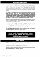
Important Safety Notice These tests ensure that the Hydrostatic Material Drive System operates to the proper specifications. All tests should be done in a safe, open area. Apply the park brake and leave the shifter in neutral unless otherwise noted. The boom and attachment should rest on the ground unless the machine is being driven. Safe working habits must be used for these checks. Refer to Operator’s Manual (Form No. 29311 ) for further information.
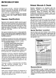
General GeneralWarning WarningInformation Information This Manual provides important information for those responsible for understanding, troubleshooting, testing, repairing and/or performing maintenance on the hydrostatic transmission drive system of 534C-9 and 534C-10 Material Handlers. NOTE! This Manual does not cover any of the implement systems of the machine.
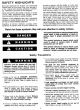
General Warning Information (continued) expect from the other, and when to expect it. 5. Be sure you understand all steps of the procedure before testing, adjusting or repairing any component or mechanical assembly. Follow the procedure carefully. 6. Always wear safety glasses, hard hat and any other locally required safety-related, protective apparel when performing testing and adjusting procedures. 7. Thoroughly clean all areas before working on them.
I. Hydraulic Oil Reservoir Make sure that the machine is level before retracting all cylinders. Proper level is to full mark +/- 1/4 inch in the sight gauge located on the outside of the reservoir. The system contains 47 gallons of hydraulic oil. Refer to the “Lubrication Specifications Chart” in the Operator’s Manual. Oil should be in good condition. See Figure 1 and Figure 2. FIGURE 1 HYDRAULIC RESERVOIR ASSEMBLY FIGURE 2 SIGHT GAUGE Form No.
II. Hydraulic Filter Condition Reason for Hydraulic Filter Condition Check Dirty suction filters can restrict oil flow to the charge pump. This can lower control pressure which can affect the machine’s ability to move, especially when ambient temperature is under 32°F. Change the hydraulic filters if they have more than 1,000 hours on them. To check hydraulic filter condition, warm the hydraulic system oil to operating temperature (minimum 100°F). Check the filter restriction indicator on the return filter.
III. Engine Speed Reason for Engine Speed Check Low engine RPM can reduce control pressure. Control pressure determines machine speed. This condition can slow machine speed at full RPM. Check engine speed with an adequate tachometer. At low idle, it should be 800-900 RPM. Adjust engine speed using the screw on the injection pump. At full throttle with no load, it should be 2500-2700 RPM. When testing engine speed, make sure the injection pump lever is contacting the stop.
III. Engine Speed (continued) FIGURE 5 BOTTOM OF FLOOR PLATE ASSEMBLY (CURRENT) Form No.
III. Engine Speed (continued) FIGURE 6 ACCELERATOR PEDAL ASSEMBLY (CURRENT) FIGURE 7 ACCELERATOR PEDAL ASSEMBLY (CURRENT) (AUXILIARY VIEW) Form No.
IV. Park Brake Reason for Park Brake Check Park brake wear can cause park brake failure and reduce braking effectiveness on a slope. With the park brake engaged, start the engine. Position the 2WD/4WD switch for two-wheel drive. With the rear wheels aligned straight ahead, move the shift lever to the forward position and run the engine full throttle (2500 RPM-2700 RPM). If the brakes are working properly, the machine will not drive through the brakes.
IV. Park Brake (continued) FIGURE 8A FRONT AXLE ASSEMBLY P/N 9114-5139 STARTING 534C-9 SERIAL NO. 0344001 534C-10 SERIAL NO. 0266001 FIGURE 8B PARK BRAKE ASSEMBLY P/N 9114-4160 Form No.
IV. Park Brake (continued) FIGURE 8C BOTTOM OF FLOOR PLATE ASSEMBLY (CURRENT) A new front axle housing went into production starting 534C-9 Serial No. 0344394 and 534C-10 Serial No. 0266057. When the new front motor design went into production, several units later the front axle housing stayed the same. The park brake is internal in the front axle differential assembly. The brake test procedure remains the same. However, the park brake components are different. See Figure 8D.
IV. Park Brake (continued) FIGURE 8D FRONT AXLE ASSEMBLY P/N 9114-3199 STARTING 534C-9 SERIAL NO. 0344394 534C-10 SERIAL NO. 0266057 FIGURE 8E DRIVE TRAIN BRAKE ASSEMBLY Form No.
V. Charge Pressure Reason for Charge Pressure Check To ensure proper park brake operation, charge pressure needs to be at proper specification. Since temperature can affect results, make certain to test system with warm oil (minimum 100°F). Control pressure is modified charge pressure. If charge pressure is low, control pressure may be low and machine speed reduced. Thus, drive performance is adversely affected by low charge pressure.
V. Charge Pressure (continued) FIGURE 9 CHARGE PRESSURE TEST PORT FIGURE 10 MAIN PUMP ASSEMBLY (SIDE VIEW) Form No.
V. Charge Pressure (continued) FIGURE 11 REAR DRIVE MOTOR ASSEMBLIES (MOUNTED) FIGURE 12 MAIN PUMP ASSEMBLY (REAR VIEW) FIGURE 11A FRONT DRIVE MOTOR (SIDE VIEW) Form No.
VI. Control Pressure Reason for Control Pressure Check To ensure control pressure is correct for proper machine speed. For the machine to move at proper engine speed, control pressure should match engine RPM. Install a low pressure gauge (1,000 PSI), hose and adapter on the drive pump control pressure Ps port. Remove the hose from port and plug. NOTE! Before starting, make sure the gauge can be observed in the operator’s cab and apply the park brake.
VI. Control Pressure (continued) FIGURE 14 MAIN PUMP ASSEMBLY (TOP VIEW) Form No.
VII. Inching Reason for Inching Check Loss of control pressure can affect machine speed. A low pressure gauge (1,000 PSI), hose, # 6 run tee and adapter should be teed into the Ps port on the drive pump. Apply the park brake and run the engine at full throttle (2500-2700 RPM). The gauge reading should be the same as in the previous control pressure test. Depress the brake pedal. The control pressure should start to fall after one-half inch of pedal travel.
VII. Inching (continued) FIGURE 16 FLOOR PLATE ASSEMBLY FIGURE 17 Form No.
VIII. Front Motor Begin Point Definition: The point at which the front motor begins to stroke toward minimum displacement. Reason for Front Motor Begin Point Check Without proper adjustment, machine speed on a flat, smooth surface will not meet specifications. The motor may not be shifting to a maximum speed position. Install a high pressure gauge (10,000 PSI), hose and adapter on MB port on the drive pump. Adjust the reverse high pressure relief valve to 3,300 PSI by loosening the locknut.
VIII. Front Motor Begin Point (continued) FIGURE 19 FRONT DRIVE MOTOR (SIDE VIEW) For our application, this drive motor is utilized in a 180 degree inversion. Form No.
IX. Drive Pump Pressure Reason for Drive Pump Pressure Check Drive pump pressure determines the drive power of the machine. Low drive pressure will result in less power. Install a high pressure gauge (10,000 PSI), hose and adapter on the MA port (located at the bottom of the drive pump). Apply the park brake and put the 2WD/4WD switch in the 2WD position. Move the shift lever to the forward position and run the engine at full throttle (2500-2700 RPM). The gauge reading should be 6,300 PSI.
IX. Drive Pump Pressure (continued) FIGURE 20A MAIN PUMP ASSEMBLY (TOP VIEW) FIGURE 22 TRACTION LOCK VALVE SCHEMATIC FIGURE 21 TRACTION LOCK VALVE Form No.
X. Machine Operation Reason for Machine Operation Check To ensure that the traction lock valve is operating correctly. Also to check for proper operation of the 2WD/4WD solenoid valve and proper begin point adjustment on the front motor. After completion of these checks, operate the machine in a flat, smooth open area. Set the machine for 4WD operation. Depress the traction lock switch. Drive the machine at full speed. Release the traction lock switch; the machine should pick up speed.
Service Notes This publication provides maintenance and service procedures for Meritor PRA 352 series planetary axles. The information contained in this publication was current at the time of printing and is subject to revision without notice or liability. 1. You must understand all procedures and instructions before you begin maintenance and service procedures. 2. You must follow your company’s maintenance and service guidelines. 3.
47 PRA 352 – Trumpet Variation No.
PRA 352 – Trumpet Variation No.
PRA 352 – Trumpet Variation No.
PRA 352 – Trumpet Variation No.
PRA 353/383 68 67 65 66 64 62 82 83 81 60 63 61 69 81 80 73 71 72 75 74 57 70 77 37 43 42 89 54 46 55 50 48 37 38 40 45 53 85 36 44 84 86 56 52 58 36 37 49 47 79 59 78 39 41 87 88 51 58 89 14 20 12 11 8 13 19 18 26 27 28 29 4 3 15 16 24 17 6 5 79 12 60 80 81 82 78 69 61 63 10 31 23 22 30 77 76 70 74 7 75 73 72 2 71 9 11 81 83 62 64 66 32 33 59 25 67 65 34 21 68 36 37 35 36 38 37 42 39 41 37 43 89 54 55 50 46 51 V 52 40 49 44 56 53
PRA 353/383 Item 1 2 3 4 5 6 7 8 9 10 11 12 13 14 15 16 17 18 19 20 21 22 23 24 25 26 27 28 29 30 31 32 33 34 35 36 37 38 39 40 41 42 43 44 45 Item Description Center Housing Differential Case Side Gear Thrust Washer Pinion Gear Thrust Washer Differential Pinion Shaft Pinion Shaft Lock Pin Washer Capscrew Bearing Cone Bearing Cup Spiral Gear and Pinion Differential Case Shim Pinion Cage Bearing Cup Bearing Cone Drive Pinion Shim Bearing Cup Bearing Cone Motor Adapter Flange Driven Sleeve Drive Sleeve Snap
PROA 352/382 (With Mechanical Drive Option) 17 16 4 36 98 99 20 18 97 1 43 19 24 26 27 2 14 13 32 23 3 15 22 37 40 7 39 94 12 38 99 93 11 8 41 9 21 34 95 10 35 4 28 6 33 5 43 96 30 45 58 31 44 42 57 52 56 54 59 51 55 29 85 53 77 49 60 84 50 86 62 63 46 65 61 47 66 83 67 82 68 48 79 87 64 89 100 78 72 88 64A 73 90 92 91 76 69 80 81 74 70 71 VII
PROA 352/382 (With Mechanical Drive Option) Item Item Description 1 2 3 4 5 6 7 8 9 10 11 12 13 14 15 Main Housing Bushing Trunnion Oil Seal Differential Case Assembly Differential Case Capscrew Differential Case Washer Side Gear Friction Discs Shim Pack Friction Drive Disc Friction Driven Discs Compression Discs Thrust Washer Pinion Gear Pinion Gear Thrust Washer Spider 16 17 18 19 20 21 22 23 24 25 26 27 28 29 30 31 32 33 34 35 36 37 38 39 40 41 42 43 44 45 46 47 48 49 50 51 Gear Capscrew Washer Gea
PROA 352/382 IX
PROA 352/382 Item 1 2 3 4 5 6 7 8 9 10 11 12 13 14 15 16 17 18 19 20 21 22 23 24 25 26 27 28 29 30 31 32 33 34 35 36 37 38 39 40 41 42 43 44 45 46 47 48 Item Description Center Housing Bushing Trunnion Oil Seal Lubrication Fitting Level Plug Drain Plug Vent Plug Hydraulic Line Bleeder Cover Capscrew M8x1,25x16,0 Differential Case Assembly Washer Capscrew M10x1,5x80,0 Drive Disc Driven Friction Disc Clutch Disc Shim Compression Disc Thrust Washer Side Gear Thrust Washer Pinion Gear Spider Spiral Gear & Pin
Table of Contents Section 1: Introduction Description ......................................................................................................................................................1 Identification Section 2: Removal and Disassembly Remove Axle ..................................................................................................................................................2 Disassemble Ball and Ramp Brake Disassemble Trumpet Assembly ..................................
Table of Contents Assemble Hydraulic Apply Brake Housing Assembly ..................................................................................38 Hydraulic Apply Brake Housing Functional Test Assemble Three Function Brake Housing Assembly ....................................................................................39 Assemble Ball and Ramp Brakes, Brake Discs, Reaction Plate and Pins ....................................................
Section 1 Introduction Description Identification The Meritor PRA 352 Series Planetary Axle is a double reduction single speed unit that has: A tag on the main housing correctly identifies basic axle specifications. • • A hypoid or spiral pinion and ring gear set When ordering parts, be sure to specify information stamped on the name plate. This information will allow easy identification of correct parts.
Section 2 Removal and Disassembly Remove Axle ! WARNING To prevent serious eye injury, always wear safe eye protection when you perform vehicle maintenance or service. ! WARNING Support vehicle with safety stands. Do not work under a vehicle only supported by jacks. Jacks can slip or fall over and cause serious personal injury.
Section 2 Removal and Disassembly ! CAUTION Loosen and remove brake cylinder capscrews alternately to avoid spring load damage to parts. 5. Disassemble brake cylinder assembly. Remove brake release capscrew. Loosen and remove brake cylinder capscrews alternately to avoid spring load to be supported by only one capscrew. 6. Remove spring, piston and O-ring seals. Do not cut or scratch them. 7. Clean cylinder and brake support surfaces. Do not damage ground surfaces. 8.
Section 2 Removal and Disassembly Disassemble Planetary System and Axle Shaft NOTE Before removing planetary gears, place housing in horizontal position or place cloth between pinion gear flange and housing flange to keep rollers from falling down into housing. To avoid mixing them, be sure to put rollers and spacers of each planetary gear in separate plastic bags. 4. Remove pinion gear flange. Lift it through planetary gear pins. 5. Remove axle shaft assembly and cone bearing. If necessary, use press.
Section 2 Removal and Disassembly Disassemble Hydraulic Apply Wet Disc Brake Disassemble Three Function Wet Disc Brake 1. Remove piston return spring capscrews. NOTE 2. Remove return springs. Do not disassemble brake piston unless necessary. 3. Remove brake piston assembly. Figure 2.9. Figure 2.9 1. Remove return spring capscrews with 4 mm Allen wrench. Remove return springs and washers. Figure 2.11. Figure 2.11 ! CAUTION Ground oil seal surfaces must be properly protected to avoid damage.
Section 2 Removal and Disassembly ! ! WARNING • Use a special tool or press to compress the brake assembly to avoid serious personal injury from the spring pressure. • Observe all WARNINGS and CAUTIONS provided by the press manufacturer concerning press operation to avoid serious personal injury and damage to components. CAUTION Before removing action plate and other parts, mark the original assembly positions of all brake piston assembly parts. This procedure will make reassembly easier. 6.
Section 2 Removal and Disassembly 8. Use sand paper on piston surfaces if they have nicks or hits. Figure 2.17. 5. Depending on ring gear position, remove pinion bearing cage capscrews. Figure 2.17 6. Remove pinion bearing cage assembly from main housing. Figure 2.19. 7. Remove drive sleeve and snap ring. Figure 2.19. Figure 2.19 Disassemble Main Housing 1. Remove adjusting nut capscrew lock. 2. Remove adjusting nut capscrew and adjusting nut. DRIVE SLEEVE & SNAP RING 8.
Section 2 Removal and Disassembly 1. Before disassembling differential case, mark position of both halves and spider cross for easier reassembly. Figure 2.21. 5. If differential case is “integral,” remove differential pinion axle lock capscrew and differential pinion axle. Then turn side gears and remove differential pinions, side gears and washers. Figures 2.23, 2.24 and 2.25. Figure 2.21 Figure 2.23 Disassemble Differential Case 2. Remove differential case capscrews. Figure 2.24 3.
Section 2 Removal and Disassembly 6. If necessary, separate ring gear from differential case. Remove capscrews and washers that fasten ring gear. With brass hammer, tap ring gear to separate it from differential case. Figures 2.26 and 2.27. 7. If differential case has two halves, remove ring gear with a press after capscrews have been removed (Figure 2.26). Use appropriate metal or wood supports. Figure 2.28. Figure 2.28 Figure 2.26 SUPPORTS Figure 2.27 8.
Section 2 Removal and Disassembly Disassemble Pinion Bearing Cage 1. If pinion bearing cage was not removed, hold yoke, flange or splined sleeve with appropriate holder to remove pinion nut. Figure 2.32 If pinion bearing cage was already removed, place it on main housing and fasten with two capscrews. ! CAUTION To avoid oil leaks, be careful not to damage the mounting surface of the bearing cage. 3. Remove pinion oil seal. Pry at several points around circumference between seal, flange and bearing cage.
Section 2 Removal and Disassembly ! CAUTION Figure 2.37 Do not use pry bar to remove bearing cage from carrier. A pry bar can damage bearing cage, shims and main housing. 5. Remove pinion bearing cage and shims from main housing. If bearing cage is tight within the main housing, hit bearing cage at several points around flange area with leather, plastic or rubber mallet. Figure 2.36. Figure 2.36 NOTE The inner bearing cone and bearing spacer will remain on the pinion shaft. 9.
Section 2 Removal and Disassembly 10. If pinion bearings need to be replaced, remove inner bearing cone from drive pinion with press or bearing puller. Puller must fit under inner face of cone to remove cone correctly without damage. Figure 2.40. Figure 2.40 NOTE If bearing cup is changed, the bearing cone must also be replaced. The cup and cone must come from the same manufacturer.
Section 3 Prepare Parts for Assembly Clean Ground and Polished Parts ! WARNING Clean Axle Assemblies • A complete axle assembly can be steam cleaned on the outside to remove dirt. • Before the axle is steam cleaned, close or put a cover over all openings in the axle assembly. Examples of openings are breathers and hydraulic inlets. To prevent serious eye injury, always wear safe eye protection when you perform vehicle maintenance or service.
Section 3 Prepare Parts for Assembly Inspect Tapered Roller Bearings Inspect the cup, cone, rollers and cage of all tapered roller bearings in the assembly. If any of the following conditions exist, the bearing must be replaced: • The center of the large diameter end of the rollers are worn level with, or below the surface. • The center of the large diameter end of the rollers are worn to a sharp edge. Figure 3.1. • Deep cracks or breaks in the cup, cone inner race or roller surfaces.
Section 3 Prepare Parts for Assembly • Damage on the cup and cone inner race surfaces that touch the rollers.Figure 3.5. Figure 3.5 SPALLING & FLAKING Inspect Main Differential Assembly Parts that are damaged must be replaced. Inspect the following parts for wear or stress. Figure 3.6. Figure 3.6 Inspect Hypoid Pinion and Ring Gear Sets ! • • CAUTION Hypoid drive pinions and ring gears are machined in matched sets.
Section 3 Prepare Parts for Assembly Inspect Main Housing • For fractures and burrs in machined areas. Inspect Yoke • For wear at seal journal area. Replace yoke, flange or sleeve if either shows too much wear at seal journal area. Inspect Planetary System Parts • For existence of cracks, pitting, breaks or sharp edges on planetary gear teeth, planetary gear axles and rollers. Inspect Brakes • For condition of friction discs, brake piston springs and internal brake housing surfaces.
Section 3 Prepare Parts for Assembly Liquid Adhesive Reassembly Meritor uses the following liquid adhesives to retain threaded fasteners: • Check the type of liquid adhesive to be used and where the adhesive is to be applied. • In threaded holes where fasteners did not require removal, check each one for tightness by applying the minimum amount of specified torque. • If fasteners do not rotate, they are tightened properly.
Section 3 Prepare Parts for Assembly Apply Silicone Gasket Material Liquid gasket material used by Meritor: • • Loctite FAG 3 5. Assemble components quickly to permit gasket material to compress evenly between parts. Figure 3.8 Neutral Silicon, Dow Corning 768 or Rhodia 567/666 • • 0.125" (3.18 MM) DIAMETER SILICONE GASKET MATERIAL BEAD Three Bond 1134 Loctite 515 ! WARNING Small amounts of acid vapor are present when applying some gasket materials.
Section 3 Prepare Parts for Assembly ! ! WARNING To avoid serious personal injury, trichloroethylene must not come in contact with your skin. Do not smoke and avoid breathing vapors in closed rooms without ventilation. Do not use trichloroethylene near flames, welding operations or hot surfaces exceeding 900°F (482°C). 1. Remove any dust, oil or foreign material from Toric ring (2), lodging ramps (4, 7), ring retention lips (3, 8), oil seal ring (1) and ring bore (5).
Section 3 Prepare Parts for Assembly 5. Verify mounting distance (A) in at least four places spaced 90 degrees apart. The difference in the mounting distance (A) around ring cannot be more than 0.04 inches (1 mm). Figure 3.15. NOTE Do not use any liquid that leaves a film of oil or does not evaporate quickly. 3. Place installation tool (9) under oil seal ring with Toric ring (2). Submerge ring in receptacle filled with trichloroethylene until entire surface of Toric ring is wet. Figure 3.13. Figure 3.
Section 3 Prepare Parts for Assembly ! • CAUTION Misalignment or a twisted Toric ring may cause leakage in the DUO-CONE oil seal. If installation was not correct, remove oil seal from bore and repeat steps 3-6. • A Toric ring must never slide on any ramp of oil seal ring or bore. To prevent sliding, wait at least two minutes for trichloroethylene to evaporate before continuing with installation. When in the correct position, Toric ring must roll only on ramps.
Section 3 Prepare Parts for Assembly • Warped ring can cause irregular pressure on ring surface resulting in oscillating movements of oil seal. • Different pressures on oil seal surfaces can cause seepage, wear and leaks. • Oscillating oil seals allow dirt to enter. Figure 3.21 shows an incorrect installation of an oil seal in its mounting position. The upper bore is stopped and the lower lodge is rotating. Figure 3.21 CL X B A Y X Figure 3.
Section 4 Assembly and Installation Assemble Differential Case ! WARNING To prevent serious eye injury, always wear safe eye protection when you perform vehicle maintenance or service. 4. Apply Loctite 271 or Three Bond 1305 adhesive to ring gear fasteners. See Section 3, “Liquid Adhesive.” Install ring gear fasteners and fasten with the specified torque, 66-75 lb-ft (90-100 N•m). Figure 4.1. T Figure 4.1 1. Apply specified lubricant on all parts of differential case assembly before installation.
Section 4 Assembly and Installation NOTE For limited slip differential, go to step 12. 7. Install spider cross, differential pinions and washers on original assembly position. Figure 4.3. d. Install differential pinion axle and lock capscrew. Fasten capscrew to specified torque 17-23 lb-ft (23-31 N•m). T 8. Install other side gear over spider and differential pinions. Figure 4.5. Figure 4.5 Figure 4.3 SPIDER a.
Section 4 Assembly and Installation 10. Apply Loctite 271 or Three Bond 1305 liquid adhesive to capscrews. Install four capscrews into case halves equally spaced and tighten to 48-64 lb-ft (64-87 N•m). T 11. Install other capscrews into case halves. Tighten the capscrews to 48-64 lb-ft (64-87 N•m). T 12. Assemble Limited Slip Differential Case. d. Place disc pack stack in vise. Use micrometer to determine “D”, the height (thickness) of limited slip disc stack (includes thrust washer and compression disc).
Section 4 Assembly and Installation f. Place removed plain half side gear on top as shown in Figure 4.10. Use depth gauge to determine “A”, distance from differential case half flange to backside of differential side gear. Take four readings. Average readings for result. Figure 4.10. g. Determine clearance dimension: B-A=(C-D)-A. Clearance dimension must be greater than 0.05 mm and less than 0.15 mm. h. Use proper shim thickness to achieve clearance specified in step G. i.
Section 4 Assembly and Installation 2. Attach torque wrench to the tool nut and rotate differential gears. As differential rotates, read torque value indicated on dial. Figure 4.13. T Figure 4.13 2. Support bearing cage with metal or wood blocks. 3. Press the bearing cup into bore of bearing cage until cup is flat against bottom of bore. Use correct size sleeve to install bearing cup. NOTE Use same procedure for both bearing cups. 4. Put drive pinion in press.
Section 4 Assembly and Installation 9. Install outer bearing cone on pinion shaft against spacer. Figure 4.16. NOTE Do not install pinion oil seal in bearing cage before bearing preload adjustment. Continue adjusting preload of pinion bearings. 5. Use appropriate tool to fasten pinion through yoke, flange or splined sleeve. Figure 4.17. Figure 4.17 10. Press outer cone bearing with 10 ton force and check preload of bearings. Figure 4.16.
Section 4 Assembly and Installation 10. After getting specified preload, remove bearing cage from main housing and disassemble yoke or input flange. ! CAUTION Make sure oil seal lips are clean and free from dirt. Dirt can cause leakage between seal and yoke or flange. 11. Install pinion oil seal with the appropriate tool: a. Apply extreme pressure lithium soap grease to oil seal lips. Figure 4.19. d. Install yoke or flange and pinion nut into pinion. e.
Section 4 Assembly and Installation 2. Record the pinion cone (PC) variation number on the old drive pinion that is being replaced. If the PC variation number cannot be located, assemble the gear set with the shim pack found in step 1. Figure 4.23. Figure 4.23 7. If the new pinion cone number is a minus (–), subtract the number from the standard shim pack thickness that was calculated in step 3 or 4. NOTE The value calculated in step 6 or 7 is the thickness of a new shim pack that will be installed.
Section 4 Assembly and Installation Install Pinion Bearing Cage Assembly on Main Housing NOTE Use minimum of three shims in pack. If pack is made from different thickness shims, install thinnest shims on both sides of pack for maximum sealing. 3. Install two capscrews and washers that fasten bearing cage. Tighten to minimum torque of 67 lb-ft (90 N•m). Figure 4.26. T Figure 4.26 1. Install correct shim pack between bearing cage and main housing. Figure 4.24. Figure 4.24 4.
Section 4 Assembly and Installation 5. If ring gear is mounted on opposite brake housing side, loosen two capscrews that fasten pinion bearing cage. Remove cage and mount it after differential case is assembled. 4. Install differential case assembly. Figure 4.29. Figure 4.29 If ring gear is mounted on brake housing side, install other capscrews that fasten pinion bearing cage. Tighten the capscrews to a torque of 67-91 lb-ft (91-120 N•m).
Section 4 Assembly and Installation 7. Install differential case bearing adjusting nut on brake housing. Figure 4.31. 8. Install pinion bearing cage assembly and shim pack. 9. Check backlash, differential preload and teeth contact. See Section 5, “Adjustments.” Install Differential Housing Assembly into Main Housing (With Adjusting Ring 2 Sides) 1. Install adjusting ring into main housing. 2. Install bearing cup.
Section 4 Assembly and Installation 7. Install pinion bearing cage assembly and shim pack. Figure 4.34. See “Install Pinion Bearing Cage Assembly on Main Housing,” page 31. Figure 4.34 9. Check backlash, differential preload and teeth contact. See Section 5, “Adjustments.” 10. If all adjustments are within specifications, remove brake housing. Apply liquid gasket material to main housing surface. ! WARNING To avoid serious personal injury, be careful when using Loctite.
Section 4 Assembly and Installation 2. Install Duo-Cone oil seal into axle shaft and into axle shaft housing bore as specified on page 18. Figure 4.37. Figure 4.39 44.60 44.80 Figure 4.37 DUO-CONE OIL SEAL ! 3. With a correct size sleeve, use a press to install flange side cone bearing. Install axle shaft into axle shaft housing. Figure 4.37. Assemble Trumpet Assembly ! WARNING WARNING To avoid serious personal injury, be careful when using Loctite.
Section 4 Assembly and Installation ! CAUTION Rollers must come from the same manufacturer and have the same tolerance range. Replace spacers and washers when a new roller is used. 3. Apply grease, Shell-71032 Alvania EP-2 or Texaco - 995 Multifak EP-2, on each gear hole. Install rollers and spacers into planetary gears. Figure 4.40. 5. Install planetary spider and axle shaft bearing adjusting nut. 6. Measure trumpet flange radius.
Section 4 Assembly and Installation 8. Check trumpet assembly preload and subtract value obtained before tightening adjusting nut. Value must be 15-35 lb-in (1.7-4 N•m). T 9. Apply Medium Torque liquid adhesive, Loctite 241 or Three Bond 1334, on adjusting nut lock capscrew threads. Install adjusting nut lock capscrew. Tighten to 17-23 lb-ft (23.0-30.5 N•m). 13. Apply liquid gasket material on contact surfaces of trumpet and ring. Figure 4.46. Figure 4.46 T 10.
Section 4 Assembly and Installation Assemble Hydraulic Apply Brake Housing Assembly NOTE • To assemble three function brake, see page 39. • To assemble ball and ramp brake, see page 43. 6. Apply high torque liquid adhesive, Loctite 271 or Three Bond 1305, to capscrew threads. Install return springs and return spring capscrews. Tighten to 80-115 lb-in (9.0-13.0 N•m). T Figure 4.49. Figure 4.49 1. Check to see if the piston lodging surfaces on brake housing is free of sharp edges, nicks and burrs.
Section 4 Assembly and Installation • • If there are no leaks, proceed to Step 4. Figure 4.51 If there are leaks, disassemble brake housing assembly, find and correct the problem. Repeat Steps 1 to 3. 4. Wait five minutes, then apply 75 to 110 psi (5.1 to 7.6 bar) to the cylinder again. “B” • If there are no leaks, the assembly is assembled correctly. • If there are leaks, find and correct the problem. Repeat the test again. Assemble Three Function Brake Housing Assembly c.
Section 4 Assembly and Installation 2. Lubricate internal brake housing surfaces, inner and outer piston surfaces and oil seal bores with SAE 90 oil. Figure 4.53. Figure 4.55 Figure 4.53 MEDIUM OIL SEAL INNER PISTON 5. Install springs into bores in inner piston. Figure 4.55. For brake with 12 springs, jump one bore each three. Figure 4.55. OUTER PISTON LARGE OIL SEAL SMALL OIL SEAL OIL SAE 90 NOTE Each piston assembly has three different sizes of oil seals: three large, one medium, one small. 3.
Section 4 Assembly and Installation ! 10. Install shim pack into brake housing. Use bolts to align holes. Figure 4.59. WARNING To avoid serious personal injury, be careful when using Loctite. Follow the manufacturer’s instructions for safe use to prevent irritation to eyes and skin. Wash after skin contact. If the Loctite gets in eyes, flush with water for 15 minutes. Have eyes checked by a doctor. Figure 4.59 GUIDE BOLTS 8.
Section 4 Assembly and Installation 14. With piston still compressed, apply 350 psi (24 bar) into parking brake to make sure oil seals fit in bores. Figure 4.61. Figure 4.61 Assemble Ball and Ramp Brakes, Brake Discs, Reaction Plate and Pins 1. Install sun gear. Figure 4.63. Figure 4.63 350 PSI (24 BAR) 15. Keep the parking brake under 350 psi (24 bar) pressure and remove the manual press and guide pins. 16.
Section 4 Assembly and Installation 4. Install stationary disc lock pins. 5. Install reaction plate with lubrication hole on down side of axle. 6. If there is an outer spacer, install it on brake housing surface. Use liquid gasket material. Assemble Three Function Brakes, Brake Discs, Reaction Plate and Pins 1. Lubricate all brake components with same oil specified for axle. See page 53.
Section 4 Assembly and Installation Assemble Three Function Brake Release Bolts and Sleeves Assemble Ball and Ramp Brake Cylinder Assembly and Install on Main Housing 1. Apply Loctite 516 on bolt threads. Figure 4.67. 1. Apply liquid gasket material FAG-3 on brake cylinder surface that fastens to brake cylinder support. Assemble brake cylinder, oil seals, piston and brake cylinder support. Tighten capscrews that fasten brake cylinder support 19-26 lb-ft (26-36 N•m). Figure 4.69. T Figure 4.
Section 4 Assembly and Installation 2. While out of the axle, connect cylinder assembly to hydraulic system. Apply 400 psi (27.6 bar) pressure to compress spring until piston is against brake cylinder. Repeat this operation four to five times to make sure there is no leakage. Figure 4.70. 4. While the cylinder is pressurized with 400 psi (27.6 bar), apply liquid adhesive, Loctite 221 or Three Bond 1341, on threads of brake shaft. Install adjusting nut until it rests against piston.
Section 4 Assembly and Installation 6. After 1.47 inch (37.0 mm) dimension is obtained, apply specified pressure to brake and check the brake torque on pinion as shown in chart. Torque Reduction Disc No. Pressure Torque PRA-382 17.08:1 06 275 psi min (19 bar min) 950-1200 lb-ft (1288.01559.0 N•m) PRA-353 46.00:1 06 275 psi min (19 bar min) 350-500 (474.5678.0 N•m) NOTE To obtain the desired brake torque, fasten or unfasten the adjusting nut. For each 0.
Section 5 Adjustments Check Ring Gear Runout Specification: 0.008 inch (0.20 mm) ! Adjust Pinion and Ring Gear Backlash Specification: 0.005-0.015 inch (0.13-0.38 mm) WARNING 1. Attach dial indicator on mounting flange of carrier. To prevent serious eye injury, always wear safe eye protection when you perform vehicle maintenance or service. 2. Set dial indicator so plunger is against a tooth surface. Figure 5.2. 1. Attach magnetic base dial indicator to mounting flange of main housing. Figure 5.1.
Section 5 Adjustments 6. Loosen one bearing adjusting ring one notch, then tighten opposite ring the same amount to keep differential roller bearing preload. Figure 5.3. Verification Procedure 1. Apply a marking compound to approximately 12 teeth of ring gear. Rotate ring gear so that the 12 gear teeth are next to drive pinion. Figure 5.5. Figure 5.3 Figure 5.5 INCREASE BACKLASH DECREASE BACKLASH NOTE When you adjust backlash, only move ring gear. Do not move drive pinion.
Section 5 Adjustments 3. Compare contact patterns on ring gear teeth to good contact patterns in Figure 5.7. If contact patterns are not satisfactory, go to Incorrect Contact Patterns on this page. Figure 5.7 The location of a good hand-rolled pattern for a used gears set must match wear pattern in ring gear. The contact pattern will be smaller in area than the wear pattern.
Section 5 Adjustments Deep Contact Pattern A deep contact pattern indicates that the drive pinion was installed too far in the carrier. Figure 5.11. Figure 5.11 Variations Along Length of Gear Teeth Adjust backlash of ring gear within specification range to move contact patterns to correct location along length of gear teeth.When toe contact pattern indicates that backlash is very low and gear is too close to drive pinion: Figure 5.13. Figure 5.
Section 5 Adjustments An acceptable contact pattern is centralized between toe and heel along the length of gear teeth. Figure 5.15. Figure 5.15 Replace Lubricant 1. Install and tighten drain plug in central housing and brake housing. T 2. Clean area around fill/level plug. Remove fill/level plug from carrier inspection cover. ! In cases where it is not possible to get a good contact pattern, the contact pattern shown in Figure 5.15 is acceptable.
Section 6 Specifications PRA 352 Series Planetary Drive Axle Oil Change Intervals and Specifications Initial Oil Change 100 operating hours ① or 1240-3100 miles (2000-5000 km) (whichever comes first) Off-Highway Operation Intervals ① Check Petroleum Oil Oil Level Change 250 1,500 operating operating hours hours ① or twice a year (whichever comes first) Synthetic Oil Change — Meritor Specification 0-84 Military Specification — Oil Description Petroleum Base SAE 10W, 20W or 10W/30 ② NOTES: ① The checkin
Section 6 Specifications Nut Lock Special Tool 13.78 in. (350.0 mm) 0.079 in. (20.0 mm) 15.55 in. (395.0 mm) 1.77 in. (45.0 mm) 0.57 in. (14.5mm) 0.078 in. R 2.0 0.197 in. (5.0 mm x 45°) 0.984 in. R 5.0 Ø 0.79 in. (Ø 20.0 mm) Ø 1.97 in. (Ø 50.0 mm) THREAD: Ø 5/8" II UNC Ø 3.15 in. (Ø 80.0 mm) 0.39 in. (10.0 mm x 45°) 1.77 in. (45.0 mm) 2.44 in. (62.0 mm) 4.53 in. (115.0 mm) Ø 0.709 in. (Ø 18.0 mm) 0.079 in. (2.0 mm) in. 47 m) 0.5 .9 m Ø 3 1 8 (Ø 13. 30°±10' Ø 3.86 in. (Ø 98.
Section 6 Specifications PROA 352/382 (With Mechanical Drive Option) 4 14 11 10 15 5 16 1 3 6 13 8 19 7 17 18 2 9 12 54
Section 6 Specifications Torque Chart - PROA 352/382 ITEM 1 2 3 4 5 6 7 8 9 10 11 DESCRIPTION/THREAD Pinion Nut - M24 x 1.5-6H Nut (Stud - Center Housing) M14 x 1.5-6H Capscrew (Differential Case) M10 x 1.5-8G Capscrew (Spiral Gear) M10 x 1.0-6G Capscrew (Pinion Cage) M12 x 1.75-8G Capscrew (Lock Adjuster Ring) M6 6G Capscrew (Adjusting Nut Lock) M8 x 1.25-6G Capscrew (Brake Housing) M8 x 1.25-6G Capscrew (Brake Releaser) M12 x 1.75-6G Capscrew (Flange Adapter) .
Section 6 Specifications PRA 352 – Trumpet Variation No.
Section 6 Specifications Torque Chart - PRA 352 ITEM 1 2 3 4 5 6 7 8 9 10 11 12 13 DESCRIPTION/THREAD Pinion Nut - M24 x 1.5-6H Capscrew (Center Housing) - M14 x 1.5-6G Nut (Stud - Center Housing) - M14 x 1.5-6H Capscrew (Differential Case) - M10 x 1.5-6G Capscrew (Spiral Gear) - M10 x 1.0-6G Capscrew (Pinion Cage) - M12 x 1.75-6G Capscrew (Lock - Adjuster Ring) - M6-6G Capscrew - Adjusting Nut Lock - M8 x 1.25-6G Bolt - Return Spring - M6 x 1.0-6G Capscrew (Planetary Pinion Axle) - M10 x 1.
Section 6 Specifications PROA 352 G2H, G2M 5 17 16 21 20 2 18 8 4 19 22 7 6 10 11 1 14 13 10 11 14 15 9 2 12 13 3 17 58
Section 6 Specifications Torque Chart - PROA 352, G2H, G2M ITEM 1 2 3 4 5 6 7 8 9 10 11 DESCRIPTION/THREAD Pinion Nut - M24 x 1.5-6H Capscrew (Center Housing) M14 x 1.5-6G Nut (Stud - Center Housing) M14 x 1.5-6H Capscrew (Differential Case) M10 x 1.5-6G Capscrew (Spiral Gear) M10 x 1.0-6G Capscrew (Pinion Cage) M12 x 1.75-6G Capscrew (Lock Adjuster Ring) M6 6G Capscrew (Adjusting Nut Lock) M8 x 1.25-6G Capscrew (Brake Housing) M8 x 1.25-6G Capscrew (Brake Cylinder Support) M8 x 1.
PowerWheel® Service Manual Model 8 Series B Double Reduction Wheel Drives AUBURN, INDIANA 46706-3499 U.S.A.
IDENTIFICATION IMPORTANT: All Power Wheel units and kits are shipped with a name plate that includes the Auburn Gear part number and order code as shown. Power Wheel® Example: ORDER CODE: 6WB13156C PART NO.: 6000236 SERIAL NO.: 143434 AuburnGear AUBURN IN U.S.A. In addition to the nameplate, Power Wheel drives are stamped with an identification number which appears on the cover or hub flange as shown.
ASSEMBLY OF POWER WHEEL STEP 1 Press new bearing cups (7 & 10) in each side of the hub (9). It is recommended that bearing cups (7 & 10) and cones (6 & 11) be replaced in sets. STEP 2 Assemble bearing cone (6) into cup (7) at seal end of hub (9) and press a new seal (5) into hub (9). Install boot seal (4) on hub (9) if unit is so equipped. STEP 3 Position spindle (3) upright on bench. Lubricate lips of seals (4) and (5) and lower hub (9) onto spindle (3).
STEP 18 Assemble the thrust washer (22) with tangs engaged with cover (25). NOTE: A small amount of grease applied to the back side of thrust washer (22) will hold washer in place. Apply a bead of silicone sealant to end face of ring gear (18) Assemble cover (25) aligning holes of cover and ring gear. Assemble the twelve 3/8-16 x 6-1/2 inch grade 8 bolts (26) and flat washers (27). Torque bolts to 45-50 ft-lbs.
ITEM NO. DESCRIPTION * NO. USED IN ASS’Y. ITEM NO. DESCRIPTION * NO. USED IN ASS’Y.
Cyclopac® Service Procedures Proper air cleaner servicing results in maximum engine protection against the ravages of dust. Proper servicing can also save time and money by maximizing filter life and dust cleaning efficiency. Two of the most common problems: A) Over Servicing.
Air Filter Service Tips 7 Important Steps to Follow The Important “Don’t” Don’t remove filter for inspection. (1) Remove the old element gently to prevent knocking dust off of it. Never rap a filter to clean it. Rapping only damages the filter.
Open Center HYDRAULIC POWER BRAKE VALVE MICO Incorporated 1911 Lee Boulevard (Zip Code 56003-2507) P.O. Box 8118/North Mankato, MN U.S.A. 56002-8118 Phone: (507) 625-6426 Facsimile: (507) 625-3212 Form No. 81-460-047 Revised 10/95 MICO West Division 701 East Francis Street (Zip Code 91761-5514) P.O. Box 9058/Ontario, CA U.S.A. 91762-9058 Phone: (909) 947-4077 Facsimile: (909) 947-6054 Printed in U.S.A.
TABLE OF CONTENTS System Schematic...........................................................................................................................Page 2 Representative Performance Data......................................................................................................Page 2 Description and Operation of Power Brake Valve......................................................................Pages 3, 4 & 5 External Dimensional Views...................................................
DESCRIPTION AND OPERATION OF THE MICO OPEN CENTER HYDRAULIC POWER BRAKE VALVE The MICO Open Center Brake Valve will provide hydraulic power braking when installed in an open center hydraulic circuit. It can be used in conjunction with other hydraulic devices such as power steering, also installed in the same circuit. Using a single pump to provide flow and pressure, the brake valve should be installed in the system circuitry, in series, between the pump relief valve and the other hydraulic devices.
Hydraulic System Pressure Equal to Brake Line Pressure RETURN LINE PRESSURE Inlet Port From Pump Land “B” BRAKE LINE PRESSURE FIGURE 4 Land “C” Land “A” CONTROLLED PRESSURE To Brake Pedal Return Line Pressure Orifice Reaction Chamber Flow Thru Port Schematic of Brake Valve in Manual Operation RETURN LINE PRESSURE FIGURE 5 Inlet Port From Pump BRAKE LINE PRESSURE Orifice Manual Brake Actuating Sleeve To Brake Pedal Pressure Regulating Sleeve Flow Thru Port is released.
one-half the brake line pressure, the PRESSURE REGULATING SPOOL shifts a minute amount and the pressure is regulated across LAND “A” and LAND “B” (Figure 4). If the pressure required by the brake valve is lower than that required by the power steering, the power steering will not normally interfere with the operation of the brake (Figure 4).
THREE OPEN CENTER HYDRAULIC POWER BRAKE VALVE DESIGNS PRIMARY CUP DESIGN The Primary Cup Design uses a residual valve. This valve will maintain a pressure of 12 - 20 PSI in the brake lines when the pedal is released. When used in drum brake systems this low pressure aids in preventing air from entering the brakes when the vehicle is at rest. RING SEAL DESIGN The Ring Seal Design is used mainly in disc brake systems.
SPECIFICATIONS CHART Brake Port Pressure Port Flow Thru Port Return Port Brake Line Pressure (with power) Flow Capacity * 06-460-520 1/2-20 UNF SAE No. 10 Complete unit replaced by 06-460-658 SAE No. 10 1/2-14 NPTF 1850 psi ± 50 psi 3-24 gpm 06-460-522 9/16-18 UNF SAE No. 10 1/2-20 UNF * 06-460-550 SAE No. 10 Complete unit replaced by 06-460-656 * 06-460-560 1/2-20 UNF SAE No. 8 Complete unit replaced by 06-460-656 9/16-18 UNF * 06-460-570 SAE No.
OPEN CENTER HYDRAULIC BRAKE VALVE PRIMARY CUP DESIGN (Refer to Figure 10) Disassembly 1. Remove boot (item 1) and pressure regulating spring assembly (item 2). CAUTION: Pressure regulating spring assembly has been set at the factory and should never be disassembled, re-adjusted or interchanged with another valve. 2. Separate end cap (item 21) from housing (item 11). CAUTION: Care must be taken as end cap is under tension of spring (item 19). Remove gasket (item 14). 3.
Items included in Repair Kit 06-459-002 FIGURE 10 Model Number Repair Kit 06-460-520 06-460-522 06-460-550 06-460-560 06-460-570 06-460-580 06-460-588 06-460-610 06-460-620 06-460-650 06-460-680 06-460-686 06-459-002 06-459-002 06-459-002 06-459-002 06-459-002 06-459-002 06-459-002 06-459-002 06-459-002 06-459-002 06-459-002 06-459-002 (9)
OPEN CENTER HYDRAULIC BRAKE VALVE RING SEAL DESIGN (Refer to Figure 11) Disassembly 1. Remove boot (item 1) and pressure regulating spring assembly (item 2). CAUTION: Pressure regulating spring assembly has been set at the factory and should never be disassembled. 2. Separate end cap (item 21) from housing (item 11). CAUTION: Care must be taken as end cap is under tension of spring (item 20). Remove gasket (item 14). 3. Remove piston & poppet assembly (item 17) and spring (item 20) from end cap (item 22).
Items included in Repair Kit 06-459-010 Items included in Repair Kit 06-459-020 FIGURE 11 NOTE: Residual Valve (item 21) is only found in Model 06-460-566.
OPEN CENTER HYDRAULIC BRAKE VALVE SLIDING PISTON DESIGN (Refer to Figure 12) Disassembly 1. Remove boot (item 1) and pressure regulating spring assembly (item 2). CAUTION: Pressure regulating spring assembly has been set at the factory and should never be disassembled. 2. Separate end cap (item 20) from housing (item 3). CAUTION: Care must be taken as end cap is under tension of spring (item 18). 3. 4. 5. 6. 7. Remove gasket (item 6).
Items included in Repair Kit 06-459-020 FIGURE 12 Model Number 06-460-642 06-460-684 Repair Kit 06-459-020 06-459-020 (13)
GENERAL SERVICE DIAGNOSIS With Engine Off -PEDAL GOES TO FLOOR 1. Brake not adjusted 1. Check adjustment 2. Air in system 2. Bleed brakes 3. Inoperative brakes 3. Check brakes 4. Blown hydraulic line 4. Check brake line 5. Worn out primary cup 5. Check by making sure brakes are properly adjusted, in good operating condition, and system well bled. If pedal continues to go to the floor, service brake valve. SPONGY PEDAL 1. Air in system 1. Bleed brakes PEDAL IS FIRM BUT STOPS TOO NEAR FLOOR 1.
PRESSURE BLEEDING PROCEDURE 1. Refer to Figure 13. Install a small BLEEDER BY-PASS LINE as shown. A 1/4” size line or hose is sufficient. 2. Start engine and allow enough time to pass for the system to become filled and thoroughly flushed with oil. 3. It is necessary to develop between 50-200 PSI at the inlet to brake valve. A method to throttle the oil will be needed if the system does not already have a secondary hydraulic device downstream from the brake valve.
MICO has made every attempt to present accurate information in catalogs, brochures and other printed material. MICO can accept no responsibility for errors from unitentional oversights that may exist. Due to a continuous program of product improvement, both materials and specifications are subject to change without notice or obligation.