
Service Manual Manual
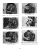
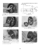
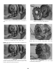
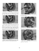
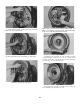
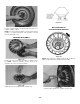
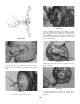
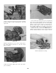

Figure 191
Install bore plug retainer ring.
Figure 194
Position new gasket on sump screen, install screen
assembly and tighten 10 to 15 ft. lbs. torque [13,6 -
20,3 N.m].
-34-
Figure 192
Position flexplate and weld nut assembly on impel-
ler cover with weld nuts toward cover. Align interme-
diate flex plate backing ring with holes impeller
cover. NOTE: Two dimples 180° apart in backing ring
must be out (toward engine flywheel). Install cap-
screws and washers.
Figure 193
Tighten flex plate capscrews 23 to 25 ft. lbs. torque
[31,2 - 33,8 N.m].
Figure 189-A
Figure 190
Position new “O” rinq on impeller cover bore plug.
Lubricate ring to facilitate reassembly. Install plug in
cover.