
Service Manual User Manual
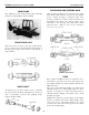
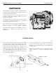
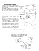
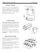
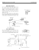
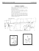
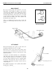
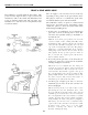
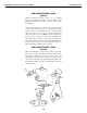
Table Of Contents
- 9020-7317 534B SERVICE MANUAL
- OPERATOR INSTRUCTIONS & LUBRICATION
- 8496 Operation & Lubrication Manual
- 8366 Operation & Lubrication Manual
- IMPORTANT SAFETY NOTICE
- INTRODUCTION
- SAFETY HIGHLIGHTS
- OPERATOR'S CAB
- CONTROL & INSTRUMENT IDENTIFICATION
- CHECKS & SERVICES BEFORE STARTING ENGINE
- ENGINE OPERATION
- WARM UP & OPERATIONAL CHECKS
- BRAKE SYSTEM
- STEERING SYSTEM
- DRIVE TRAIN
- MATERIAL HANDLING
- OPERATING PROCEDURES & TECHNIQUES
- PARKING
- STORAGE
- LUBRICATION & MAINTENANCE DIAGRAM
- 28327 Preventive Maintenance Chart
- HYDRAULIC SYSTEM
- 8497 System Operation Manual
- COVER
- NOMENCLATURE
- CAB CONTROLS AND GAGES
- ENGINE
- MAIN FRAME
- FRONT DRIVE AXLE
- DRIVE SHAFT
- REAR DRIVE AND STEERING AXLE
- TIRES
- TRANSMISSION & TORQUE CONVERTER
- STEERING CIRCUIT
- HYDRAULIC SERVICE BRAKE
- MECHANICAL PARKING BRAKE
- HYDRAULIC SYSTEM
- HYDRAULIC RESERVOIR
- HYDRAULIC PUMP
- MAIN CONTROL VALVE BANK
- MAIN PUMP CIRCUIT
- PILOT PUMP CIRCUIT
- HYDRAULIC CYLINDERS
- SWAY CIRCUIT
- LIFT CIRCUIT
- FRONT & REAR WHEEL DRIVE
- FORWARD / REVERSE LEVER (Neutral)
- FORWARD / REVERSE LEVER (Activated)
- INCHING
- TILT & COMPENSATING CIRCUITS
- OIL COOLER CIRCUIT
- CROWD (Boom In-Out) CIRCUIT
- AUXILIARY HYDRAULIC SYSTEM
- BOOM SECTIONS
- BOOM SLIDER PADS
- BOOM CROWD (IN-OUT) MOVEMENT
- MANUAL "QUICK-SWITCH" ASSEMBLY
- ELECTRICAL
- FUEL TANK
- 8369 System Operation Manual
- COVER
- NOMENCLATURE
- CAB CONTROLS AND GAGES
- ENGINE
- MAIN FRAME
- FRONT DRIVE AXLE
- DRIVE SHAFT
- REAR DRIVE AND STEERING AXLE
- TIRES
- TRANSMISSION & TORQUE CONVERTER
- STEERING CIRCUIT
- HYDRAULIC SERVICE BRAKES
- MECHANICAL PARKING BRAKE
- HYDRAULIC SYSTEM
- HYDRAULIC RESERVOIR
- HYDRAULIC PUMPS
- MAIN CONTROL VALVE BANK
- MAIN PUMP CIRCUITS
- PILOT PUMP CIRCUIT
- HYDRAULIC CYLINDERS
- SWAY CIRCUIT
- LIFT CIRCUIT
- FRONT & REAR WHEEL DRIVE
- FORWARD / REVERSE LEVER (Neutral)
- FORWARD / REVERSE LEVER (Activated)
- INCHING
- TILT & COMPENSATING CIRCUITS
- OIL COOLER CIRCUIT
- CROWD (Boom In-Out) CIRCUITS
- AUXILIARY HYDRAULIC SYSTEM
- BOOM SECTIONS
- BOOM SLIDER PADS
- BOOM CROWD (IN-OUT) MOVEMENT
- MANUAL "QUICK-SWITCH" ASSEMBLY
- ELECTRICAL
- FUEL TANK
- 81-515-009 Mico Sliding Caliper Disc Brakes Service Manual
- 81-600-001 Mico Guidelines for Installing Hydraulic Brake Components
- 81-950-016 Mico Brake Service Procedures
- 81-460-159 Mico Hydraulic Brake Valve
- 8497 System Operation Manual
- TESTING & ADJUSTING
- TROUBLE SHOOTING
- TRANSMISSION & TORQUE CONVERTER
- SM HR 182-3 Clark 18000 Series Powershift Transmission
- HOW THE UNITS OPERATE
- SECTIONAL VIEWS AND PARTS IDENTIFICATION
- DISASSEMBLY OF TRANSMISSION
- CLUTCH DISASSEMBLY
- CLEANING AND INSPECTION
- REASSEMBLY OF TRANSMISSION
- SERVICING MACHINE AFTER TRANSMISSION OVERHAUL
- TOWING OR PUSH STARTING
- SPECIFICATIONS AND SERVICE DATA
- LUBRICATION
- TROUBLESHOOTING GUIDE
- TYPICAL TWO AND THREE SPEED POWER FLOW
- PRESSURE CHECK POINTS
- CLUTCH AND GEAR ARRANGEMENT
- DRIVE PLATE INSTALLATION
- TRANSMISSION TO ENGINE INSTALLATION PROCEDURE
- SPEED SENSOR BUSHING INSTALLATION
- SM HR 182-3 Clark 18000 Series Powershift Transmission
- MISCELLANEOUS
- OPERATOR INSTRUCTIONS & LUBRICATION
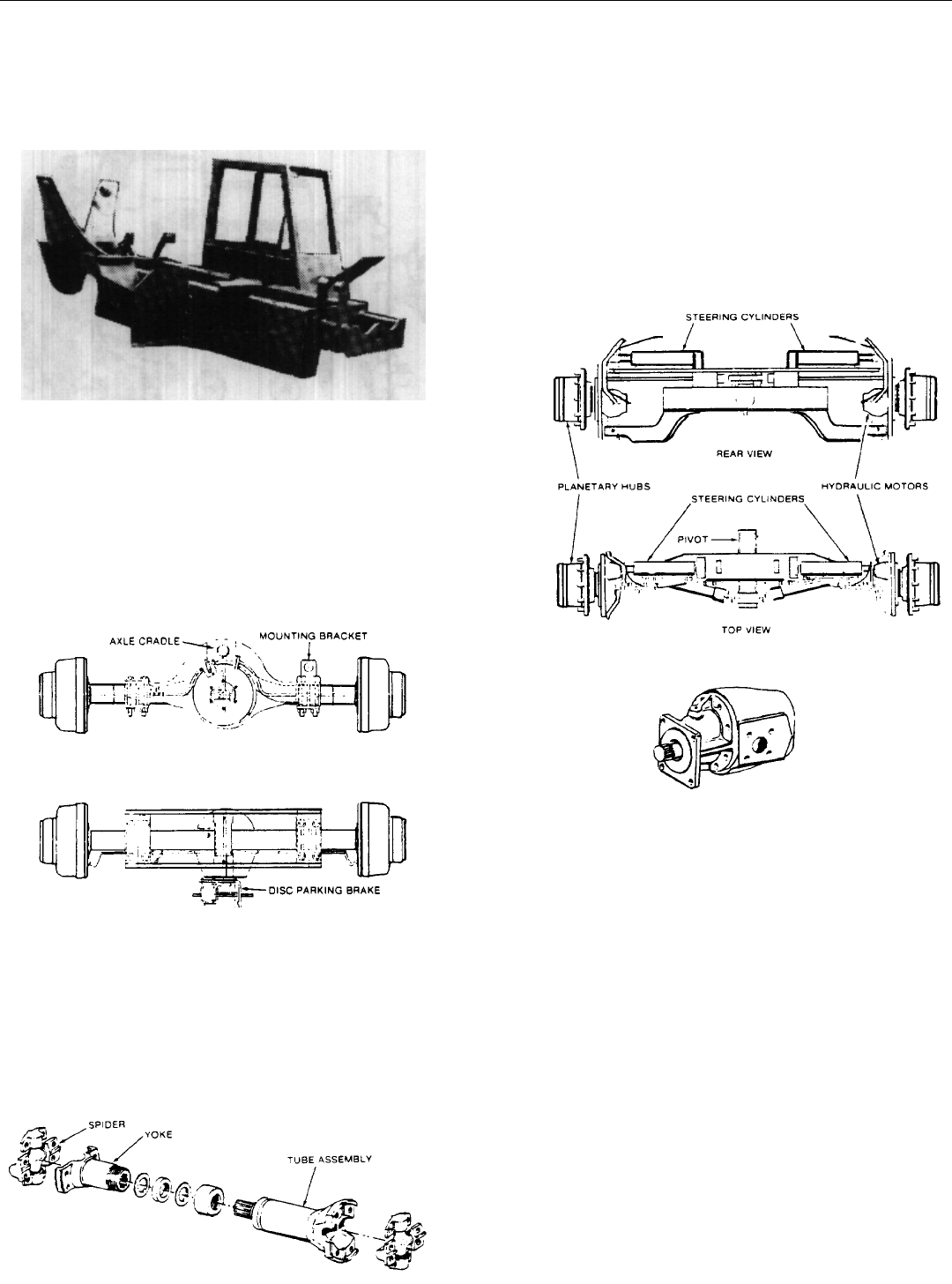
REAR DRIVE AND STEERING AXLE
The rear axle assembly pivots up and down on the
main frame. Each wheel is powered by a hydraulic
motor, driving through a planetary hub. Two
steering cylinders are used to turn the wheels. At
maximum turn radius, the outside wheel turns
about 90° to the pivoting axle. The inside wheel
turns about 87°. When in 3rd gear, the hydraulic
motors are not powered.
TIRES
Four 13:00 x 24-8PR, G3 tires are standard. 15.5 x
25-8 PR are optional on the front. The larger tires
give higher floatation in sand and mud. All tires are
inflated to 55 psi.
The tires on the Model 534B-8 are filled with
calcium chloride for counterweight. Each tire has a
mixture of 49 gallons of water and 245 pounds of
calcium chloride. Thump sound check once a week
and after tire repair.
NOTE: Tires must be properly filled on all 534B-8
models to handle rated loads. When filling, keep
valve stem at top. The fluid should be at a level
covering the valve stem. This protects the wheel
from corrosion and rusting.
MAIN FRAME
The 534B has an all welded main frame with 850
pounds of counterweight on rear for stability.
FRONT DRIVE AXLE
The front axle is bolted to the axle cradle which
pivots on the front of the main frame. The angle of
the axle (left or right) to the frame is controlled by a
sway cylinder.
DRIVE SHAFT
An automotive type drive shaft is used to transmit
the rotary motion from the transmission to the front
axle. A manually operated disc parking brake
bolted to the drive shaft.
GRADALL LOED MATERIALS HANDLER 534B SYSTEM OPERATION
5
HYDRAULIC MOTORS